Electric connector

A technology for electrical connectors and electrical connections, applied in connection, fixed connections, circuits, etc., can solve problems affecting the production efficiency of electrical connectors, achieve simple structure, reduce manufacturing costs and difficulties, and simplify the manufacturing process.

Inactive Publication Date: 2017-08-25
DEYI PRECISION ELECTRONIC IND CO LTD PANYU
View PDF7 Cites 2 Cited by
  • Summary
  • Abstract
  • Description
  • Claims
  • Application Information

AI Technical Summary

Problems solved by technology

However, in order to solder the solder balls on the terminals, they must go through the tin furnace for heating, which requires the equipment for positioning the solder balls and the equipment for transporting the electrical connector through the tin furnace, thus affecting the production efficiency of the electrical connector.

Method used


Image

  • Electric connector
  • Electric connector
  • Electric connector

Examples


Embodiment Construction

[0031] In order to facilitate a better understanding of the purpose, structure, features, and effects of the present invention, the present invention will now be further described in conjunction with the accompanying drawings and specific embodiments.

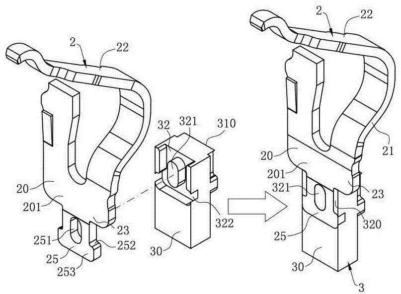
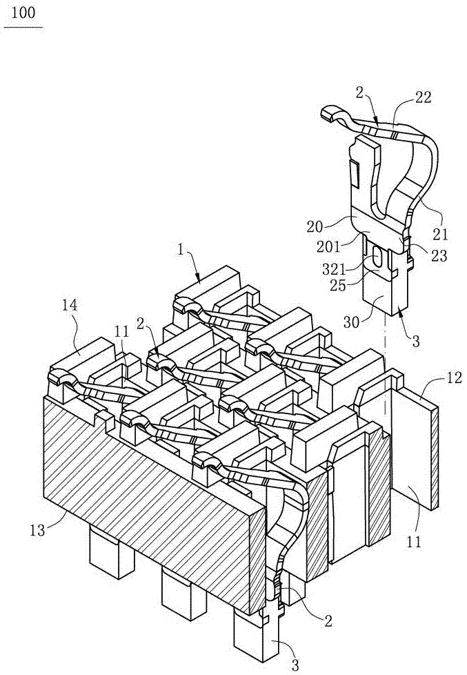
[0032] Such as Figure 1 to Figure 5 Shown is the first embodiment of the electrical connector 100 of the present invention, which is used to electrically connect a chip module 200 to a circuit board 300, including an insulating body 1; a plurality of terminals 2 accommodated in the insulating body 1; a plurality of Solder 3, each of the solder 3 is fixed to the terminal 2 respectively.

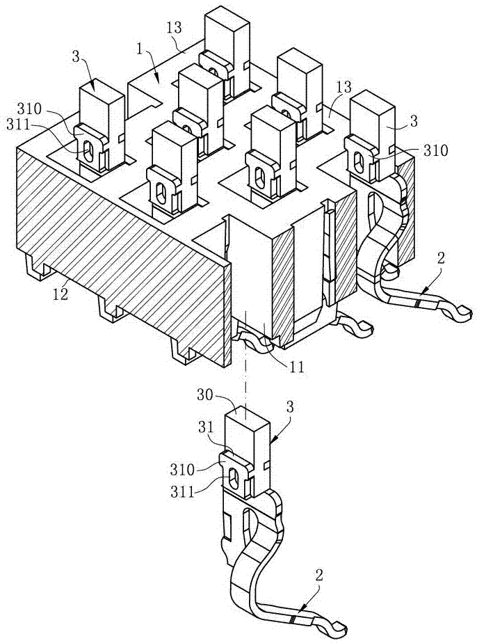
[0033] Such as figure 2 with image 3 As shown, the insulating body 1 has an upper surface 12 and a lower surface 13 which are arranged oppositely, and the insulating body 1 has a plurality of through holes 11 which are arranged in a row and are dislocated, passing through the upper surface 12 and the lower surface 13, and the upper surface...


PUM


Abstract

The invention discloses an electrical connector, comprising: an insulating body; a plurality of terminals respectively accommodated in the insulating body, each terminal has a welding part, and the welding part has a first surface and a receiving hole Through the first surface; a plurality of solders, each of which has an outer wall and an inner wall located on one side of the first surface, the inner wall is attached to the first surface, and the inner wall is attached to the first surface. The outer wall is pressed toward the inner wall, so that the outer wall is recessed toward the inner wall to form a groove, and the inner wall protrudes corresponding to the groove to form a protrusion to be accommodated in the receiving hole, so that the solder squeezes After being pressed, it can closely fit with the welding part to generate an interference effect and fix the terminal. The structure of the terminal is simple, which reduces the manufacturing cost and difficulty of the terminal.

Description

technical field [0001] The invention relates to an electrical connector, in particular to an electrical connector in which the solder is fixed to a terminal by extruding the solder with a jig. Background technique [0002] A conventional electrical connector includes a body with a plurality of receiving holes, and a plurality of terminals fixed in the plurality of receiving holes, and a plurality of solder balls are fixed to the terminals by heating and welding. However, in order to solder the solder balls on the terminals, they must go through the tin furnace for heating, which requires the equipment for positioning the solder balls and the equipment for transporting the electrical connector through the tin furnace, thus affecting the production efficiency of the electrical connector. [0003] Therefore, it is necessary to design a new electrical connector to overcome the above problems. Contents of the invention [0004] In view of the problems faced by the background t...

Claims


Application Information

Patent Timeline
IPC IPC(8): H01R13/02H01R12/52H01R12/55
CPCH01R13/02H01R12/52H01R12/55
Inventor 朱德祥
Owner DEYI PRECISION ELECTRONIC IND CO LTD PANYU
Why Eureka
Try Eureka