
Wire harness drawing and pulling shear device

A cutting device and wire harness technology, applied in the field of wire harness cutting, can solve the problems of inconvenient peeling processing, time-consuming and labor-intensive, inconsistent length, etc.

Inactive Publication Date: 2017-08-25
WUHU BOKANG ELECTRICAL
View PDF5 Cites 0 Cited by
  • Summary
  • Abstract
  • Description
  • Claims
  • Application Information

AI Technical Summary

Problems solved by technology

[0002] In the process of manufacturing automotive wiring harnesses, it is necessary to cut the purchased wire harnesses into sections. The traditional way is that workers use pliers or cutting machines to cut, and manually use rulers to measure and cut with pliers, which is time-consuming and labor-intensive. The length is not uniform, and the efficiency is low. Cutting in rolls with a cutting machine will result in severe deformation and burrs at the cutting point, which is inconvenient for subsequent peeling.

Method used


Image

  • Wire harness drawing and pulling shear device
  • Wire harness drawing and pulling shear device
  • Wire harness drawing and pulling shear device

Examples


Embodiment Construction

[0015] The specific embodiment of the present invention will be described in further detail by describing the embodiments below with reference to the accompanying drawings, the purpose is to help those skilled in the art to have a more complete, accurate and in-depth understanding of the concept and technical solutions of the present invention, and contribute to its implementation.

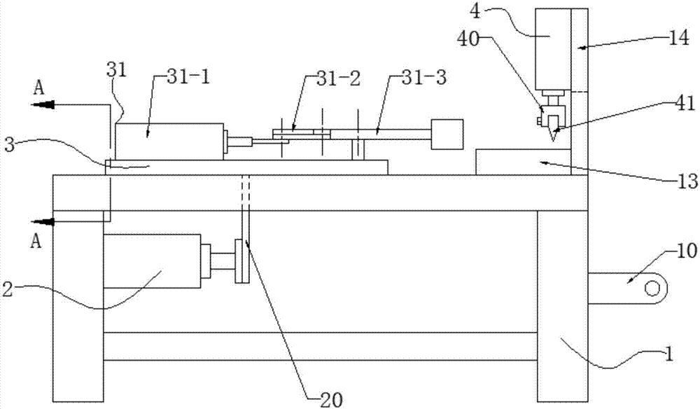
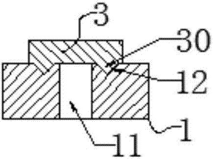
[0016] Such as Figure 1 to Figure 3 As shown, the present invention is a wire harness drawing and shearing device, which realizes the shearing operation of the coiled wire harness, ensures the uniformity of the length of the wire harness, and facilitates the subsequent binding operation.

[0017] Specifically, if Figure 1 to Figure 3 As shown, including frame 1, cylinder one 2, slide table 3 and cylinder three 4, such as figure 1 , figure 2 As shown, the side of the frame 1 is provided with a winding hanger 10, and the middle of the upper end of the frame 1 is provided with a long groove 11,...


PUM


Abstract

The invention discloses a wire harness drawing and shearing device, which comprises a frame, a cylinder one, a slide table and a cylinder three. There are two parallel "V" grooves on the end surface, and a column plate is provided at the right end of the frame. The first cylinder is connected to the frame, the slide table is slidingly connected to the "V" groove on the upper end surface of the frame, and the third cylinder is connected to the column plate. Connection, the piston rod output end of cylinder one is provided with a push rod, the push rod is connected with the lower end of the sliding table, the lower part of cylinder three is provided with an anvil block, the anvil block is fixedly connected with the frame, there is a notch in the middle of the column plate, and the lower end surface of the sliding table There are two "V"-shaped guide rails in parallel, and the slide table is slidably connected with the "V"-shaped groove through the "V"-shaped guide rails. The upper end of the slide table is equipped with a clamping mechanism, and the end of the piston rod of the cylinder three is equipped with a knife holder. , There is a blade on the knife holder to realize the cutting operation of the coiled wire harness, to ensure the uniformity of the length of the wire harness, and to facilitate the subsequent binding operation.

Description

technical field [0001] The invention belongs to the technical field of wire harness cutting, in particular, the invention relates to a wire harness drawing and shearing device. Background technique [0002] In the process of manufacturing automotive wiring harnesses, it is necessary to cut the purchased wire harnesses into sections. The traditional way is that workers use pliers or cutting machines to cut, and manually use rulers to measure and cut with pliers, which is time-consuming and labor-intensive. The length is not uniform, and the efficiency is low. Cutting in rolls with a cutting machine will result in severe deformation and burrs at the cut-off point, which is inconvenient for subsequent peeling treatment. Contents of the invention [0003] The invention provides a wire harness drawing and shearing device, which realizes the cutting operation of the coiled wire harness, ensures the uniformity of the length of the wire harness, and facilitates the subsequent bind...

Claims


Application Information

Patent Timeline
IPC IPC(8): B21F11/00B21F23/00
CPCB21F11/00B21F23/00
Inventor 朱磊马能发李华郑凯邱亮亮施其兵方良周前宽张冲张静冯瑞叶立新张建军杨开文
Owner WUHU BOKANG ELECTRICAL
Learn More