
Highly efficient heat dissipation motor rotor structure

A motor rotor and rotor technology, applied in the magnetic circuit shape/style/structure, magnetic circuit rotating parts, etc., can solve the problems of increasing the excitation loss of the motor rotor, reducing the motor efficiency, poor safety, etc., and achieving a stable permanent magnet working temperature. , Improve the efficiency of the motor and improve the service life

Pending Publication Date: 2017-08-22
GUANGDONG LIANSU MACHINERY MFG
View PDF6 Cites 0 Cited by
  • Summary
  • Abstract
  • Description
  • Claims
  • Application Information

AI Technical Summary

Problems solved by technology

However, too high rotor temperature is easy to transfer heat to the bearing through the motor shaft, reducing the service life of the bearing
[0003] For asynchronous motors, the high-temperature rotor will cause the resistance of the motor rotor winding to increase, which will increase the excitation loss of the motor rotor and reduce the efficiency of the motor.
For permanent magnet synchronous motors, the high temperature rotor will cause the magnetic properties of the permanent magnets to decline, and even directly lead to the demagnetization of the permanent magnets, which is a fatal threat to the permanent magnet motors
[0004] At present, some motors at home and abroad adopt an open heat dissipation method (air is directly blown into the air gap between the rotor and the stator). Although this heat dissipation method can more effectively dissipate heat from the stator and rotor of the motor, it has high requirements for the working environment. Long-term work in a humid and dust-polluted environment can easily lead to short service life of the motor armature and block the air gap to affect the normal operation of the motor
[0005] There are also some foreign manufacturers who inject liquid into the stator and rotor of the motor at the same time. Although such a structure can effectively cool the motor for the rotor, due to the complex structure and the seal of the rotor structure after a long period of high-speed rotation, it will definitely cause certain damage to the motor shaft. At this time, the leakage in the cooling circuit of the rotor is very easy to cause the motor to be burned, and the safety is poor.

Method used


Image

  • Highly efficient heat dissipation motor rotor structure
  • Highly efficient heat dissipation motor rotor structure
  • Highly efficient heat dissipation motor rotor structure

Examples


Embodiment

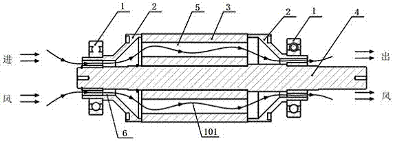
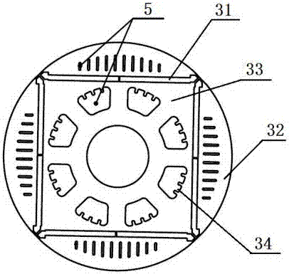
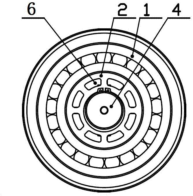
[0034] Such as figure 1 and figure 2 As shown, a high-efficiency heat dissipation motor rotor structure includes a rotor 3 and a rotating shaft 4 located at the center of the rotor 3. The rotor 3 is provided with a number of rotor cooling air passages 5; Cover 2, and there is a ventilation flow channel 6 between the rotor wind cover 2 and the rotating shaft 4; the ventilation flow channel 6 between the rotor wind cover 2 and the rotating shaft 4 and the rotor cooling air flow channel 5 in the rotor 3 are jointly formed Rotor cooling air duct 101.

[0035] Such as image 3 and Figure 4 As shown, the rotor windshield 2 includes an integrally formed clamping shaft portion 21 and a horn portion 22, the clamping shaft portion 21 is used for passing the rotating shaft 4, and the bearing 1 is sleeved on the outside, and the opening of the horn portion 22 is relatively large. The large end is in contact with the outer surface of the rotor 3; eight fan blades 23 are evenly distri...


PUM


Abstract

The invention discloses a highly efficient heat dissipation motor rotor structure. The structure comprises a rotor and a spindle arranged in the center of the rotor. Multiple rotor heat dissipation wind flow channels are arranged in the rotor. Rotor wind covers are arranged on two ends of the rotor. Air passing flow channel are arranged between the rotor wind covers and the spindle. The air passing flow channels between the rotor wind covers and the spindle and the rotor heat dissipation wind flow channels in the rotor form rotor heat dissipation wind channels. According to the invention, energy is saved; consumption is reduced;, heat is highly efficiently radiated; the structure is simple; and service lifetime of the motor can be prolonged.

Description

technical field [0001] The invention relates to the field of motor rotors, in particular to a motor rotor structure with high heat dissipation. Background technique [0002] At present, at home and abroad, because the inner rotor of the motor is in a state of high-speed rotation during work, it basically does not dissipate heat. However, an excessively high rotor temperature can easily transfer heat to the bearing through the motor shaft and reduce the service life of the bearing. [0003] For asynchronous motors, the high-temperature rotor will cause the resistance of the motor rotor winding to increase, thereby increasing the excitation loss of the motor rotor and reducing the efficiency of the motor. For permanent magnet synchronous motors, the high temperature rotor will cause the magnetic performance of the permanent magnets of the motor to decline, and even directly lead to the demagnetization of the permanent magnets, which is a fatal threat to the permanent magnet m...

Claims


Application Information

Patent Timeline
IPC IPC(8): H02K1/32
CPCH02K1/32
Inventor 魏巍黄正雄
Owner GUANGDONG LIANSU MACHINERY MFG
Learn More