Self-retaining type deadlocking device
A self-holding and locking technology, which is applied in the direction of electromechanical devices, control mechanical energy, electrical components, etc., can solve problems such as poor reliability, interference and braking failure, and failure to maintain the locked state of the motor shaft, achieving a tight contact and locked state Firm and energy-free to maintain the effect of unlocking the locked state
- Summary
- Abstract
- Description
- Claims
- Application Information
AI Technical Summary
Problems solved by technology
Method used
Image
Examples
Embodiment 1
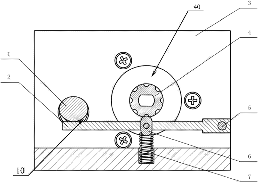
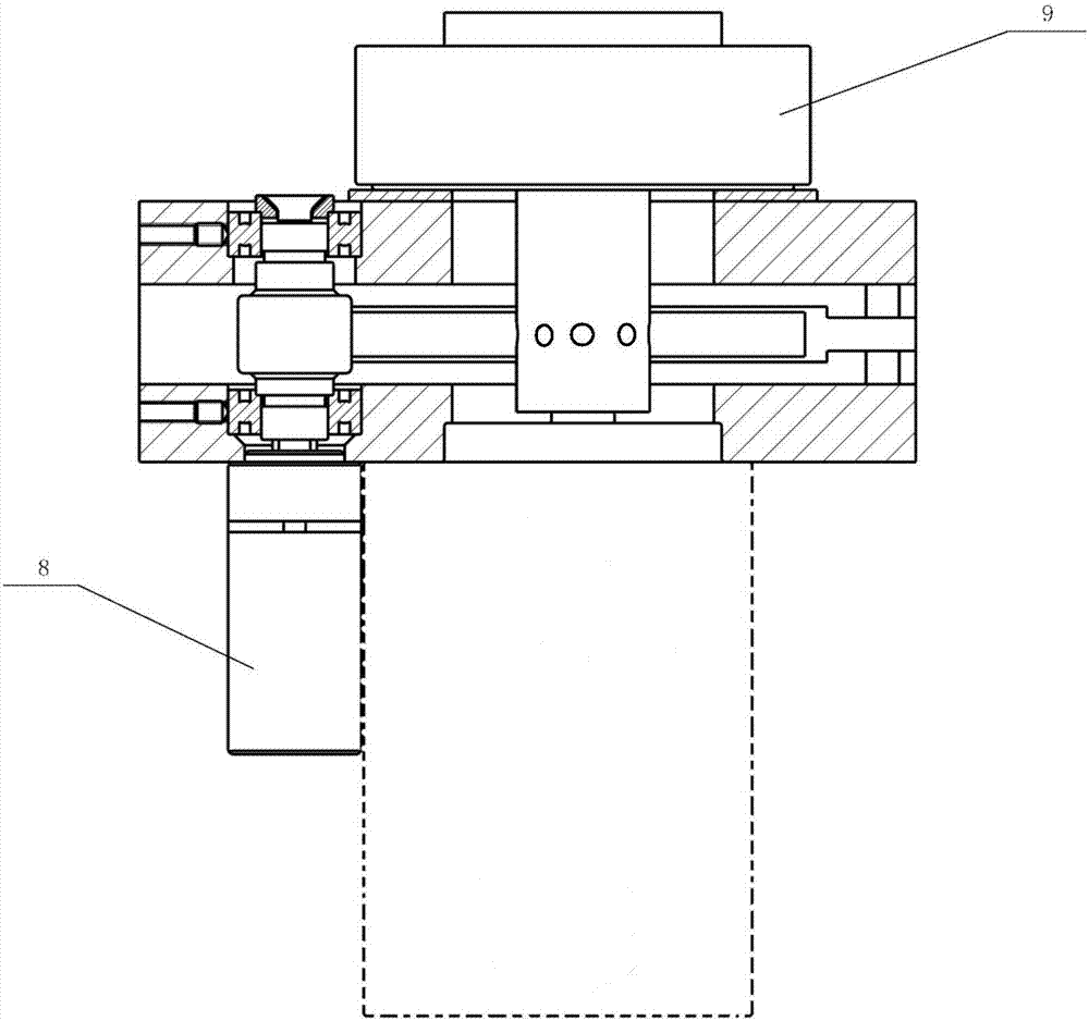
[0022] Example 1, such as Figure 1-2 As shown, this embodiment discloses a self-holding locking device, the device includes a base 3, a pin 5 is arranged on the base 3 and a swing rod 2 that can swing around the pin 5 is installed on the swing rod 2 One end of the thimble 6 is connected to the surface of the base 3 through a spring 7, and the other end extends into the motor shaft cavity 40 in the base 3, and the motor shaft outside the base is inserted into the above-mentioned motor shaft cavity and can freely rotate therein. A shaft coupling 4 with grooves distributed on the mounting surface is fixed on the part where the rotating shaft is inserted into the motor rotating shaft cavity, and a camshaft cavity 10 is also provided on the same side of the swing rod 2 where the motor rotating shaft cavity 40 is located in the base body 3, that is, the motor rotating shaft cavity 40 and The camshaft cavity 10 is on the upper side of the swing rod 2. The camshaft outside the base i...
Embodiment 2
[0027]Embodiment 2, the difference between this embodiment and Embodiment 1 is that a camshaft cavity is also provided on the opposite side of the swing rod where the motor shaft cavity is located in the base, that is, the motor shaft cavity is on the upper side of the swing rod and the camshaft cavity is on the swing rod The camshaft outside the base is inserted into the above-mentioned camshaft cavity and can rotate freely in it. The position of the cam installed on the camshaft is opposite to the swing rod. When the cam rotates to its protruding part driven by the camshaft When it is not pressed against the swing rod, under the action of spring tension, the thimble is separated from the groove on the coupling so that the motor shaft can rotate. , the spring can be stretched to make the thimble contact the groove on the coupling so that the motor shaft cannot rotate.
[0028] The working process of the self-holding locking device disclosed in this embodiment is:
[0029] Wh...
PUM
 Abstract
Description
Claims
Application Information
 - Generate Ideas
- Intellectual Property
- Life Sciences
- Materials
- Tech Scout
- Unparalleled Data Quality
- Higher Quality Content
- 60% Fewer Hallucinations
Browse by: Latest US Patents, China's latest patents, Technical Efficacy Thesaurus, Application Domain, Technology Topic, Popular Technical Reports.
© 2025 PatSnap. All rights reserved.Legal|Privacy policy|Modern Slavery Act Transparency Statement|Sitemap|About US| Contact US: help@patsnap.com


