
Steel wire rope locking device

A wire rope locking technology, which is applied in the field of wire rope locking devices, can solve problems such as easy slipping, unstoppable, and wire rope cannot be locked.

Pending Publication Date: 2020-03-06
SHANGHAI SHENGXIANG SCI & TECH
View PDF0 Cites 0 Cited by
  • Summary
  • Abstract
  • Description
  • Claims
  • Application Information

AI Technical Summary

Problems solved by technology

When the pulling force is greater, the force of jacking will be greater, but there will be situations where it cannot withstand it. The disadvantage is that the deformation is positively correlated with the thickness of the wire rope. The jacking block has a fixed point, and the distance between the jacking block and the wire rope The distance is also very accurate, for example, the accuracy of 10 microns
Therefore, the wire rope will not be able to be locked or easily slipped after locking

Method used


Image

  • Steel wire rope locking device
  • Steel wire rope locking device
  • Steel wire rope locking device

Examples


Embodiment Construction

[0022] The following description serves to disclose the present invention to enable those skilled in the art to carry out the present invention. The preferred embodiments described below are only examples, and those skilled in the art can devise other obvious variations. The basic principles of the present invention defined in the following description can be applied to other embodiments, variations, improvements, equivalents and other technical solutions without departing from the spirit and scope of the present invention.

[0023] Those skilled in the art should understand that in the disclosure of the present invention, the terms "vertical", "transverse", "upper", "lower", "front", "rear", "left", "right", " The orientation or positional relationship indicated by "vertical", "horizontal", "top", "bottom", "inner", "outer", etc. is based on the orientation or positional relationship shown in the drawings, which are only for the convenience of describing the present invention...


PUM


Abstract

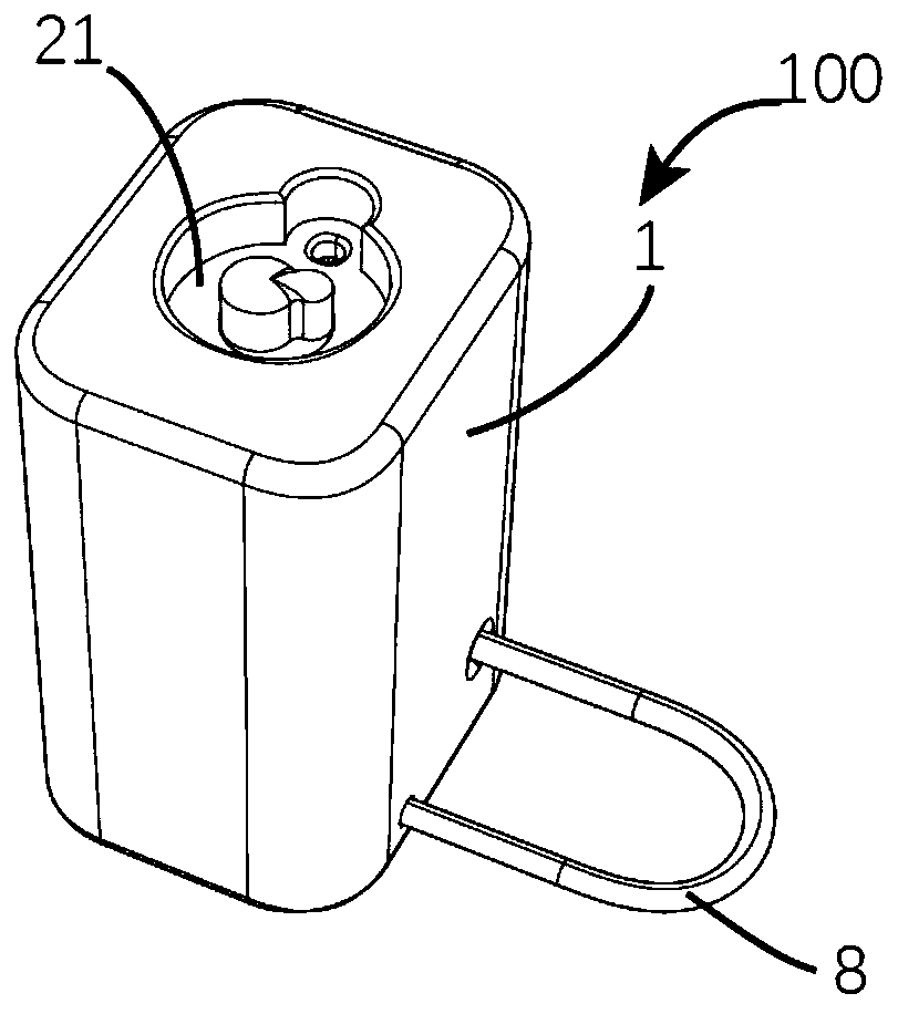
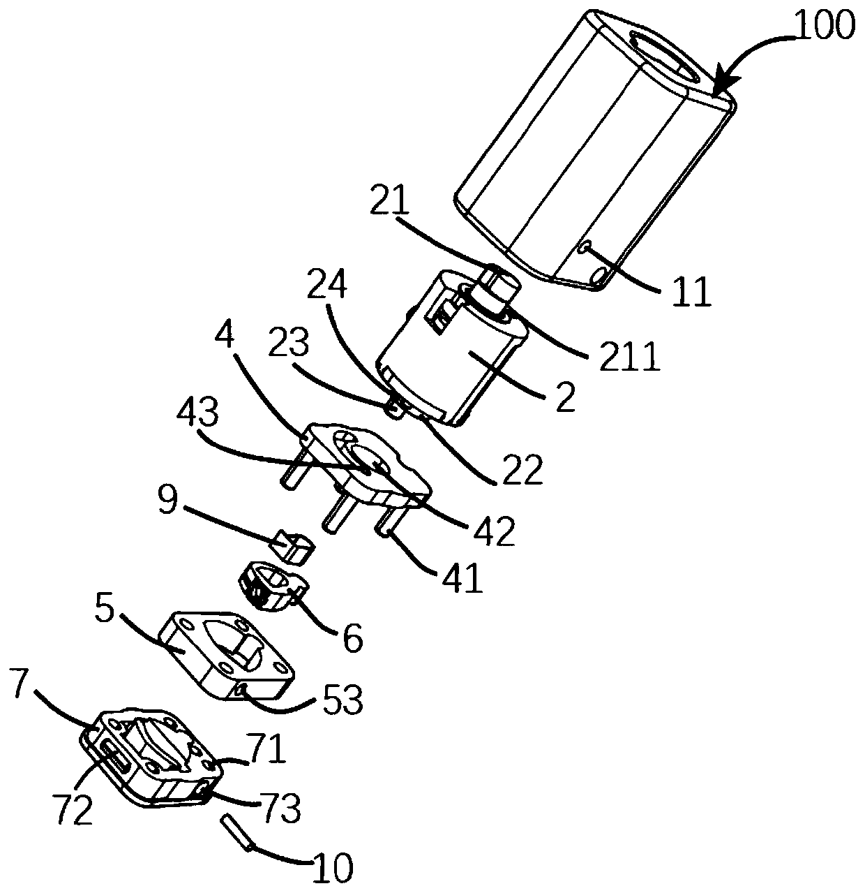
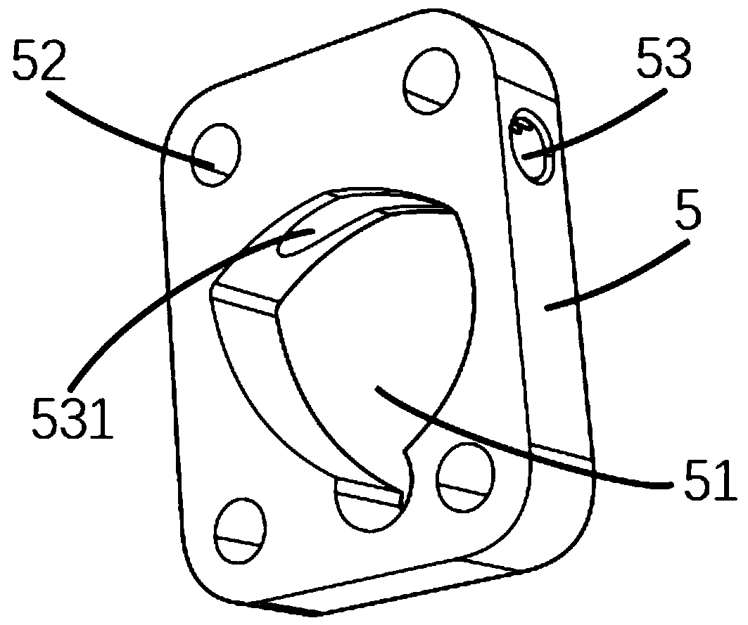
A steel wire rope locking device comprises a shell, an eccentric block, a top block, a sealing cover and a steel wire rope. The eccentric block and the top block are arranged in the shell. An eccentric groove is formed in the eccentric body. The top block is arranged in the eccentric groove. The sealing cover is connected with the shell. The steel wire rope is connected with the sealing cover. Thetop block comprises a locking end and a top block body. The top block body extends to the locking end to form an eccentric shaft insertion hole. The locking end is provided with a top block groove and an antiskid protrusion. In the locking state of the steel wire rope locking device, the steel wire rope penetrates through the top block groove of the locking end and is pressed into the top block groove of the top block, the antiskid protrusion of the locking end clamps the steel wire rope, and therefore the top block locks the steel wire rope, wherein an NdFeB magnet is arranged in the top block groove of the top block.

Description

technical field [0001] The invention relates to the technical field of lead seals, in particular to a wire rope locking device. Background technique [0002] Lead seals are generally used to block parts that need to be locked, such as dosage equipment or goods, to ensure that the lock is not illegally opened during use or during transportation. It is not only suitable for transportation fields such as railways, highways, ports, and aviation, but also for energy measurement industries such as power supply, construction period, and water supply, as well as for ordnance sealing, chemical industry, mining, finance, containers, foreign trade commodity inspection, and enterprise product packaging. Inspection, anti-theft and leakage of secrets and other fields, the scope of application is very wide. [0003] There are teeth and grooves on the top block of the existing wire rope locking device. The wire rope passes through the groove, and the wire rope is pressed in the groove, an...

Claims


Application Information

Patent Timeline
Patent Type & Authority Applications(China)
IPC IPC(8): E05B39/00
CPCE05B39/00E05B15/1614
Inventor 鲍成番孙佳炜潘才林
Owner SHANGHAI SHENGXIANG SCI & TECH
Learn More