


Quick Research
Generate reliable direction feasibility study reports for your R&D in just a few steps.

Technical Q&A
Discover and master advanced knowledge NOW. Basics, ideas, possibilities, all at once.

Find Solutions
As an expert in R&D theories, this can generate solutions to your technical problems instantly.

Evaluate Feasibility
Analyze your overall solution with one click, know your potential R&D risks in advance.

Monitor Landscape
Get weekly tech updates, stay abreast of the latest tech innovations and key insights.
Oil dipstick having temperature adjustment function
A technology of temperature regulation and dipstick, which is applied in the direction of using electric means for temperature control, auxiliary controller with auxiliary heating device, level indicator for level members, etc. Large, low temperature of oil in the ruler tube, etc., to avoid errors
- Summary
- Abstract
- Description
- Claims
- Application Information
AI Technical Summary
Problems solved by technology
Method used
Image

Examples
Embodiment 1
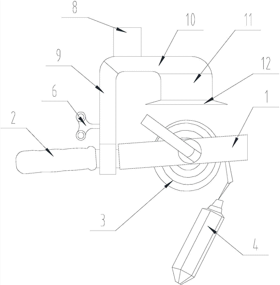
[0031] Such as Figure 1-Figure 2 As shown, the oil dipstick with temperature adjustment function of the present invention includes a dipstick body, and the dipstick body includes a ruler frame 1, a handle 2 installed on one side of the ruler frame 1, and a ruler wound on the ruler frame 1. Band 3 and chi tuo 4 connected with one end of ruler belt 3 are provided with an air guide tube assembly near one end of the ruler belt 3 on the handle 2. One end of the air guide tube assembly is open and its open end faces the ruler belt 3 to guide the wind. The other end of the barrel assembly is connected to the handle 2;
[0032] A blowing device 5 and a driving device 6 are provided at one end close to the handle 2 in the inner cavity of the air guide tube assembly;
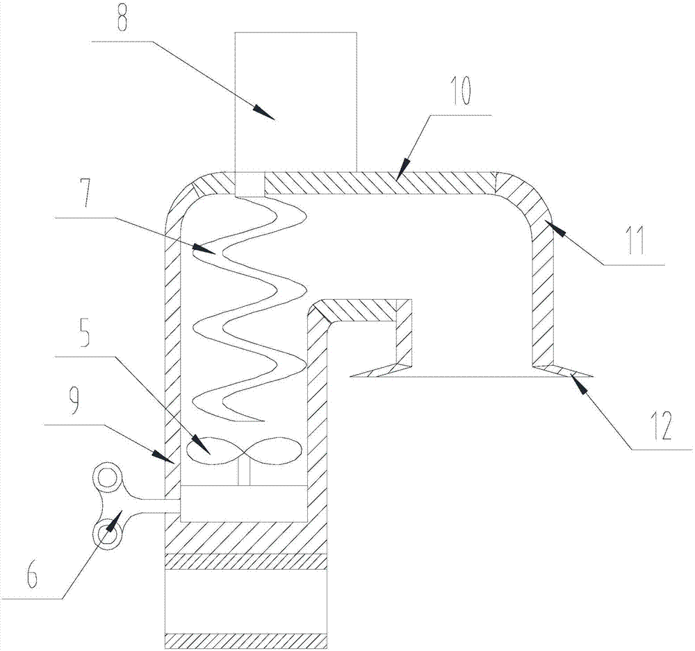
[0033] In the inner cavity, a heating device 7 and an energy supply device 8 are arranged between the blowing device 5 and the opening, and the energy supply device 8 provides energy for the heating device 7 so that the...
Embodiment 2
[0036] The present invention is based on embodiment 1, and the present invention is further described.
[0037] Such as Figure 1-Figure 2 As shown, the present invention has a temperature-adjusting oil dipstick, and the air guiding cylinder assembly includes a mounting cylinder 9, a horizontal cylinder 10, and a guiding cylinder 11 that are sequentially communicated with each other, and one end of the mounting cylinder 9 is perpendicular to the handle 2 connection, the other end of the installation cylinder 9 is connected to the guide cylinder 11 through the horizontal cylinder 10, and the axis of the horizontal cylinder 10 is parallel to the axis of the handle 2, the axis of the guide cylinder 11 is parallel to the axis of the installation cylinder 9, and the guide cylinder 11 The end away from the horizontal cylinder 10 faces the ruler tape 3;
[0038] Both the blowing device 5 and the driving device 6 are located at the end of the inner cavity of the installation cylinder...
Embodiment 3
[0041] The present invention is based on embodiment 1, and the present invention is further described.
[0042] Such as Figure 1-Figure 2 As shown, the present invention has a temperature regulating oil dipstick, the blowing device 5 is a fan, and the driving device 6 is a clockwork device. When the coiled steel strip of the clockwork device is unclamped, the fan blades of the fan rotate.
[0043]Open flames and the activation of ordinary electronic equipment are prohibited around the oil tank to avoid contact with air when the electronic equipment is activated, which may cause a fire. Setting the driving device 6 as a clockwork device avoids sparks when the motor is started and ensures the safety of the staff.
[0044] Further, the heating device 7 includes a heating resistance wire and a serpentine tube with both ends closed, one end of the resistance wire passes through the wall of the serpentine tube and is located in the serpentine tube, and the other end of the resista...
PUM
 Abstract
Description
Claims
Application Information
 - R&D Engineer
- R&D Manager
- IP Professional
- Industry Leading Data Capabilities
- Powerful AI technology
- Patent DNA Extraction
Browse by: Latest US Patents, China's latest patents, Technical Efficacy Thesaurus, Application Domain, Technology Topic, Popular Technical Reports.
© 2024 PatSnap. All rights reserved.Legal|Privacy policy|Modern Slavery Act Transparency Statement|Sitemap|About US| Contact US: help@patsnap.com