
Illuminating device for building construction

A technology for lighting devices and building construction, which is applied in the direction of lighting devices, lighting devices, fixed lighting devices, etc., and can solve problems such as long power supply connection lines, reduced work efficiency, and damage to the insulation skin of power supply lines.

Active Publication Date: 2017-08-18
北京东方中远市政工程有限责任公司
View PDF4 Cites 0 Cited by
  • Summary
  • Abstract
  • Description
  • Claims
  • Application Information

AI Technical Summary

Problems solved by technology

[0002] In the actual construction of the construction site, due to the tight schedule or construction needs, construction needs to be carried out at night, so the lighting on the construction site has become an indispensable tool in the construction process. However, due to the long power supply connection required in the construction lighting process , making it extremely difficult to take in and out the wires, increasing the workload and reducing work efficiency. At the same time, when not in use, the power supply wires are exposed to the outside world for a long time and are vulnerable to various accidental damages, such as people trampled on, hard objects scratches, etc., resulting in power supply failures. The outer insulation of the line is damaged, resulting in a decrease in the service life of the power supply line. In addition, in some existing construction sites with a relatively long construction period, in order to improve the safety of power supply and lighting, an electric leakage alarm is generally installed on the construction lighting device to achieve However, these alarms are generally exposed and without any protective measures, and are easily damaged by external factors, which brings stability to the use of lighting.

Method used


Image

  • Illuminating device for building construction
  • Illuminating device for building construction
  • Illuminating device for building construction

Examples


Embodiment Construction

[0018] All features disclosed in this specification, or steps in all methods or processes disclosed, may be combined in any manner, except for mutually exclusive features and / or steps.

[0019] Any feature disclosed in this specification (including any appended claims, abstract and drawings), unless expressly stated otherwise, may be replaced by alternative features which are equivalent or serve a similar purpose. That is, unless expressly stated otherwise, each feature is one example only of a series of equivalent or similar features.

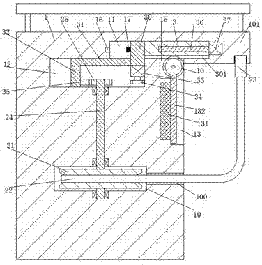
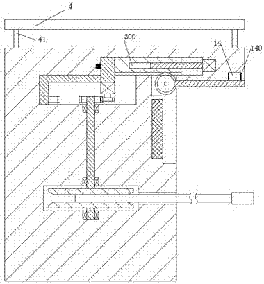
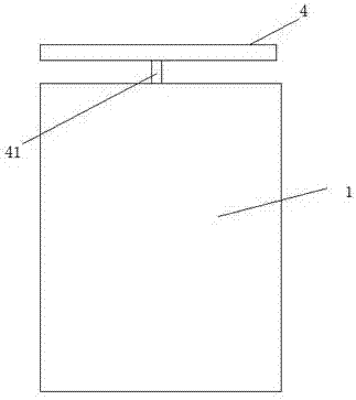
[0020] Such as Figure 1-3 As shown, a lighting device for building construction of the present invention includes a box body 1, an assembly plate 101 is provided at the upper right end of the box body 1, and an engaging groove 14 with the opening end facing downward is provided on the lower end surface of the assembly plate 101. , the box 1 is provided with a cavity 10 and a perforation 100 communicating with the cavity 10, a rotating rod 24...


PUM


Abstract

The invention discloses an illuminating device for building construction. The illuminating device comprises a box body, and an assembly plate is arranged at the right upper end of the box body; a cavity and a penetrating hole which communicates with the cavity are formed in the box body; a rotating rod is movably mounted in the cavity; a coiling wheel is fixedly mounted on the rotating rod; an electric wire is coiled on the coiling wheel; a first slide pushing groove which extends into the assembly plate is formed in the box body; a slide pushing plate which can move left and right is mounted in the first slide pushing groove; a second slide pushing groove which communicates with the first slide pushing groove is formed in the position, below the first slide pushing groove, in the box body; a second slide pushing plate which can move left and right is mounted in the second slide pushing groove; a first slide pushing block is fixedly mounted at the left end of the slide pushing plate; the lower end of the first slide pushing block stretches into the second slide pushing groove; a push rod is fixedly connected between the lower end of the first slide pushing block and the second slide pushing block; a first power device is fixedly mounted at the lower end of the first slide pushing block; and a first toothed chain wheel is mounted on the first power device.

Description

technical field [0001] The invention relates to the technical field of construction lighting, in particular to a lighting device for building construction. Background technique [0002] In the actual construction of the construction site, due to the tight schedule or construction needs, construction needs to be carried out at night, so the lighting on the construction site has become an indispensable tool in the construction process. However, due to the long power supply connection required in the construction lighting process , making it extremely difficult to take in and out the wires, increasing the workload and reducing work efficiency. At the same time, when not in use, the power supply wires are exposed to the outside world for a long time and are vulnerable to various accidental damages, such as people trampled on, hard objects scratches, etc., resulting in power supply failures. The outer insulation of the line is damaged, resulting in a decrease in the service life ...

Claims


Application Information

Patent Timeline
Patent Type & Authority Applications(China)
IPC IPC(8): F21S8/06F21V23/00F21V23/06F21V33/00F21W131/402F21Y115/10
CPCF21S8/061F21S8/068F21V23/002F21V23/06F21V33/0076F21W2131/402
Inventor 何建龙
Owner 北京东方中远市政工程有限责任公司
Learn More