Tensioning structure of transmission chain of pneumatic tyred roller and adjusting method of tensioning structure

A technology for tire rollers and transmission chains, applied in the directions of transmissions, belts/chains/gears, mechanical equipment, etc., can solve the problems of high torque, thread seizure, cumbersome process, etc., and achieve the effect of simple structure and convenient maintenance.

Active Publication Date: 2017-08-18
柳工无锡路面机械有限公司
View PDF5 Cites 0 Cited by
  • Summary
  • Abstract
  • Description
  • Claims
  • Application Information

AI Technical Summary

Problems solved by technology

[0005] The above-mentioned adjustment method realizes the tensioning process of the chain is relatively cumbersome, and the screw connection gap between the drive axle support 102 and the fine-threaded screw 101 is small, and it is necessary to adjust the fine-threaded screw 101 at one end first, and only a small distance can be adjusted, and then adjust At the other end, otherwise, the phenomenon of thread seizure will occur, so it is necessary to adjust the left and right fine-threaded screws 101 in small distances repeatedly to lift the drive axle support 102; when the fine-threaded screws 101 at both ends are adjusted to the appropriate position, tighten the four Compression bolt 103; due to the compact structure of the tire roller, the frame is a fully enclosed integral frame, and the fine-threaded screw 101 tool on the inner side is difficult to reach the operating position, and the adjustment can only be realized after disassembling the water tank and other accessories; the fine-threaded screw The positioning surface at the bottom of 101 is in contact with the frame. Since the weight of the drive axle increases the friction on the contact surface, a large torque is required to adjust the fine threaded screw, and a large air gun is required for adjustment on the construction site. Adjust the four fine-toothed screws 101; therefore, the amount of work to adjust the chain is large and the adjustment is difficult

Method used


Image

  • Tensioning structure of transmission chain of pneumatic tyred roller and adjusting method of tensioning structure
  • Tensioning structure of transmission chain of pneumatic tyred roller and adjusting method of tensioning structure

Examples


Embodiment Construction

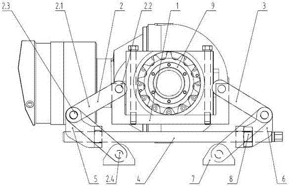
[0022] see figure 1 , a tire roller drive chain tensioning structure related to the present invention, said structure includes a sprocket 9 installed on the drive axle support 1;

[0023] A screw 4 is horizontally arranged below the drive axle support 1, and the left and right ends of the screw 4 are respectively screwed with a guiding left-handed thread block 5 and a guiding right-handed thread block 6,

[0024] The left connecting rod assembly 2 includes two connecting rods 2.1, the top of the upper connecting rod 2.1 is hinged to the drive axle support 1 at the hinge point 1 2.2, and the bottom of the connecting rod 2.1 located at the bottom is hinged at the hinge point 3 with the frame 7 2.4, the bottom of the upper connecting rod 2.1 and the top of the lower connecting rod 2.1 are hinged to the guide left-handed threaded block 5 through hinge point 2 2.3;

[0025] The right connecting rod assembly 3 includes two connecting rods, the top of the connecting rod at the top ...


PUM


Abstract

The invention discloses a tensioning structure of a transmission chain of a pneumatic tyred roller and an adjusting method of the tensioning structure. The tensioning structure comprises a chain wheel (9) installed on a driving axle supporting seat (1). A screw (4) is transversely arranged below the driving axle supporting seat (1), a guiding left-hand thread block (5) and a guiding right-hand thread block (6) are rotatably arranged at both the left and the right ends of the screw (4) correspondingly, and the guiding left-hand thread block (5) and the guiding right-hand thread block (6) are connected with the driving axle supporting seat (1) through a left connecting rod assembly (2) and a right connecting rod assembly (3) correspondingly. According to the tensioning structure of the transmission chain of the pneumatic tyred roller and the adjusting method of the tensioning structure, the structure is simple, the tensioning process is simple, and the operation is convenient, so that the maintaining performance of the transmission chain is promoted.

Description

technical field [0001] The invention relates to a tensioning structure and an adjusting method thereof, in particular to a mechanism for tensioning a transmission chain on a tire roller and an adjusting method thereof, belonging to the field of road engineering machinery. Background technique [0002] At present, the tire roller has become an indispensable compaction mechanical engineering equipment in asphalt pavement construction because of its good flexible compaction performance and will not damage the compacted aggregate during the compaction process. Compaction on asphalt pavement and compaction of stabilized soil roadbed; [0003] The common driving form of domestic tire rollers is mainly rear wheel drive. The drive axle drives the rear wheel driven sprocket through the transmission chain for transmission. The manufacturing and installation precision requirements of the chain drive are low, the carrying capacity is large, and there is a certain degree of buffering and...

Claims


Application Information

Patent Timeline
Patent Type & Authority Applications(China)
IPC IPC(8): F16H7/08
CPCF16H7/08F16H2007/0842
Inventor 孙甜甜徐彪程观润陈云宇李文帅
Owner 柳工无锡路面机械有限公司
Why Eureka
Try Eureka