
Power failure brake

A brake, electric technology, applied in the direction of the brake type, brake parts, brake actuators, etc., can solve the problems of large volume and large heat generation of the brake frame and brake parts, so as to ensure the braking ability and ensure the The effect of accuracy

Pending Publication Date: 2017-08-18
SHAOXING IND SCI DESIGN & RES INST CO LTD
View PDF0 Cites 7 Cited by
  • Summary
  • Abstract
  • Description
  • Claims
  • Application Information

AI Technical Summary

Problems solved by technology

Because the existing brakes are braked by the friction torque generated by mechanical movement, the brake frame and brake parts are large in size and generate a lot of heat during the braking process.

Method used


Image

  • Power failure brake
  • Power failure brake
  • Power failure brake

Examples


Embodiment Construction

[0016] The technical solutions of the present invention will be further specifically described below through the embodiments and in conjunction with the accompanying drawings.

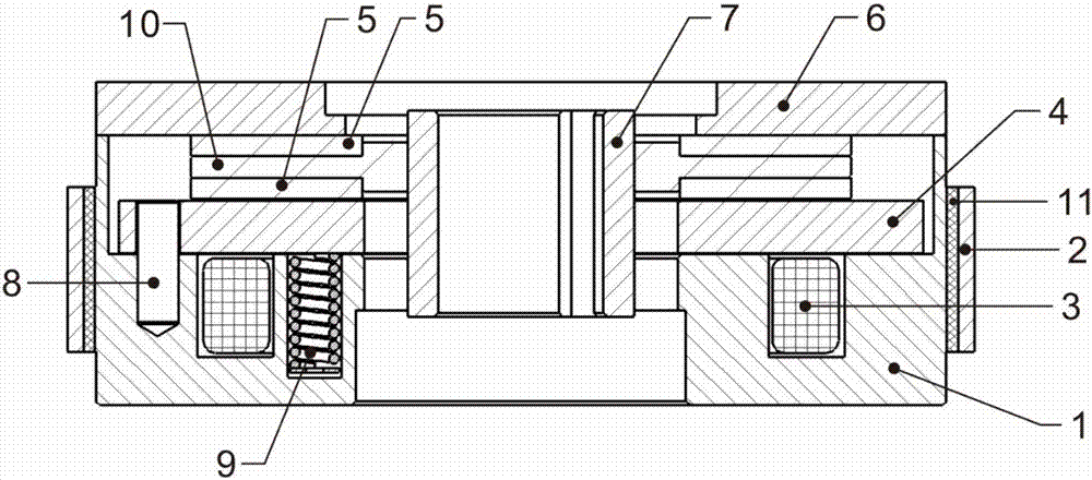
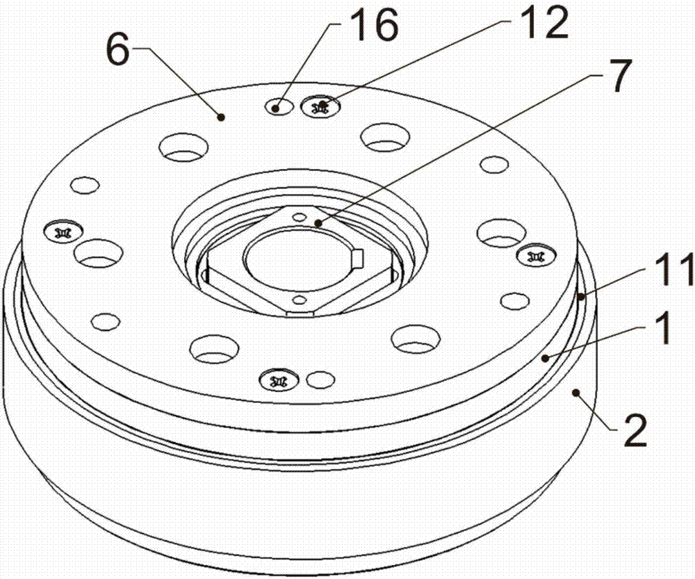
[0017] Such as Figure 1 to Figure 5 As shown, the de-energized brake includes a yoke 1 with a built-in coil slot 14, an excitation coil 3 is arranged in the coil slot 14, an armature 4 is placed on the inner end surface of the yoke 1, and a cover plate is connected to one end of the yoke 1 6. An intermediate body 10 connecting the transmission block 7 is provided between the cover plate 6 and the armature 4. The intermediate body 10 is made of iron, and the inner wall of the intermediate body 10 is closely matched with the transmission block 7. The intermediate body 10 Friction bodies 5 are provided at both ends, and the outer diameter of the friction body 5 is the same as that of the intermediate body 10. The inner end surface of the yoke 1 is provided with a plurality of spring seats 13 and spring p...


PUM


Abstract

The invention discloses a power failure brake. The power failure brake comprises a magnetic yoke with a coil groove inside; a magnet exciting coil is arranged in the coil groove; a gag bit is positioned on the inner end surface of the magnetic yoke; one end of the magnetic yoke is connected with a cover plate; a middle body connected with a transmission block is arranged between the cover plate and the gag bit; friction bodies are arranged at two ends of the middle body; multiple spring bases and elastic pin bases are arranged on the inner end surface of the magnetic yoke; springs are mounted in the spring bases; elastic pins are mounted in the elastic pin bases; and one ends of the elastic pins are fixed on the elastic pin bases. The power failure brake is small in size, reasonable in layout, excellent in braking performance and high in environment adaptability.

Description

technical field [0001] The invention relates to a power-off brake, which belongs to the technical field of brake manufacture. Background technique [0002] Existing brakes are mainly composed of a brake frame, brake parts, and a control device. By controlling the control device, the brake parts move to generate friction, thereby realizing braking. Because the existing brake is braked by the moment of friction generated by mechanical movement, the volume of the brake frame and the brake parts is large, and the heat generated during the braking process is relatively large. Contents of the invention [0003] The purpose of the present invention is to provide a de-energized brake with reasonable design, small volume, good braking performance and strong heat dissipation. [0004] The technical solution of the present invention is: a de-energized brake, including a magnetic yoke with a built-in coil slot, an excitation coil is arranged in the coil slot, and an armature placed o...

Claims


Application Information

Patent Timeline
Patent Type & Authority Applications(China)
IPC IPC(8): F16D65/14F16D65/78F16D121/20
CPCF16D65/14F16D65/78F16D2121/20F16D2065/788
Inventor 张永明
Owner SHAOXING IND SCI DESIGN & RES INST CO LTD
Learn More