
Centrifugal clutch

A technology of centrifugal clutches and dampers, applied in clutches, automatic clutches, mechanical equipment, etc., can solve problems such as difficult separation

Active Publication Date: 2017-08-18
广东奥硕智能装备有限公司
View PDF9 Cites 2 Cited by
  • Summary
  • Abstract
  • Description
  • Claims
  • Application Information

AI Technical Summary

Problems solved by technology

[0002] The existing centrifugal (brake, speed limit) device can realize the meshing of the active part and the driven part when the rotating speed reaches a certain value, and realize the braking by using the principle of centrifugal when the rotating speed reaches a certain value; but most of the structures are suitable for meshing, which is not easy separate

Method used


Image

  • Centrifugal clutch
  • Centrifugal clutch
  • Centrifugal clutch

Examples


Embodiment Construction

[0018] The present invention will be further described below in conjunction with accompanying drawing and specific embodiment:

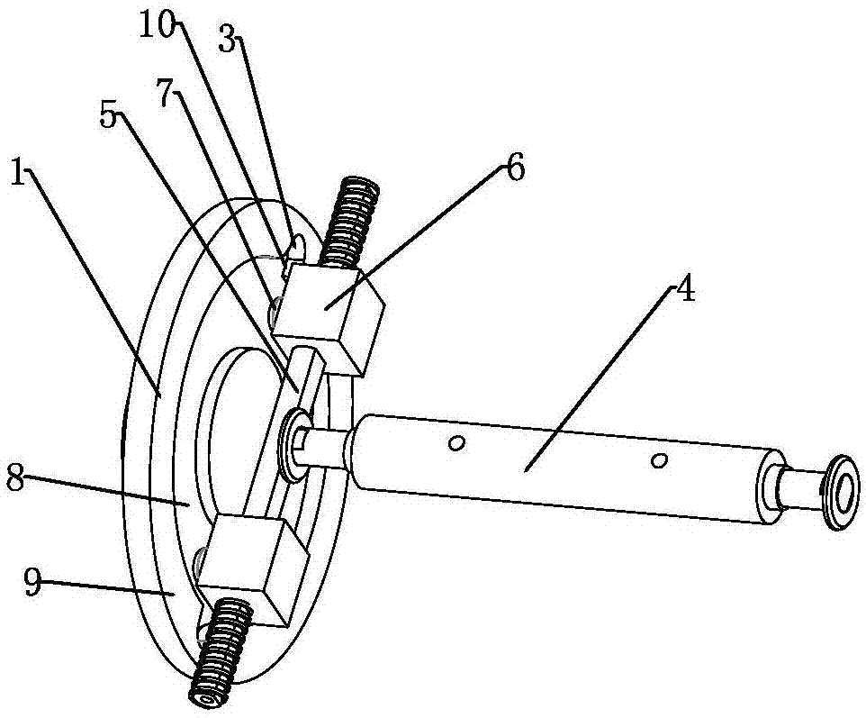
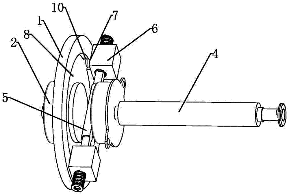
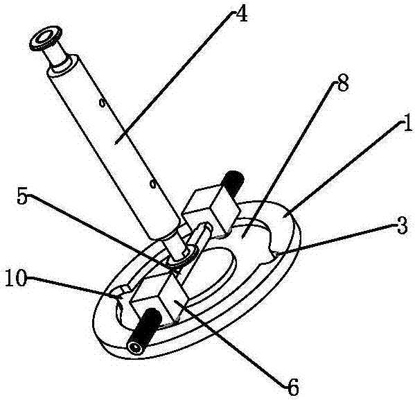
[0019] A centrifugal clutch as shown in the figure includes a driven shaft end plate 1 and a damper 2 arranged on the driven shaft end plate 1 . A slot 3 is provided on the end plate 1 of the driven shaft, a drive shaft 4 is provided on a surface opposite to the slot 3 , and a slide bar 5 is connected to one end of the drive shaft 4 . A counterweight 6 and a spring for restoring the counterweight 6 can be slid in the axial direction on the slide bar 5 , and a post 7 that can be snapped into the card slot 3 is provided on the counterweight 6 . In this case, the rotation of the driving shaft is used to drive the slide bar to rotate, and the counterweight is sleeved on the slide bar. When the slide bar is rotating, under the action of centrifugal force, the counterweight block will overcome the force of the return spring and slide out to the end of the...


PUM


Abstract

The invention relates to a centrifugal clutch which comprises a driven shaft end plate and a damper arranged on the driven shaft end plate. Clamping grooves are formed in the driven shaft end plate, and a driving shaft is arranged on the face, opposite to the clamping grooves, of the driven shaft end plate; one end of the driving shaft is connected with a sliding rod; the sliding rod is provided with a balance weight in the axial direction in a sliding mode and a spring used for making the balance weight reset; and the balance weight is provided with clamping columns capable of entering the clamping grooves. The centrifugal clutch has the advantages of good engagement and disengagement effects, simple structure and the like.

Description

technical field [0001] The invention relates to a centrifugal clutch. Background technique [0002] The existing centrifugal (brake, speed limit) device can realize the meshing of the active part and the driven part when the rotating speed reaches a certain value, and realize the braking by using the principle of centrifugal when the rotating speed reaches a certain value; but most of the structures are suitable for meshing, which is not easy separate. Contents of the invention [0003] Aiming at the deficiencies of the prior art, the present invention aims to provide a centrifugal clutch with good separation and meshing effect and simple structure. [0004] In order to solve the problems of the technologies described above, the technical solution adopted in the present invention is: [0005] A centrifugal clutch, characterized in that it includes a driven shaft end plate 1 and a damper 2 arranged on the driven shaft end plate 1; One side of the drive shaft 4 is provide...

Claims


Application Information

Patent Timeline
Patent Type & Authority Applications(China)
IPC IPC(8): F16D43/06
CPCF16D43/06
Inventor 王阳陈波涛黄坤煌郑泽彬覃木钊李俊斌曾祥旺
Owner 广东奥硕智能装备有限公司
Learn More