Reciprocating oscillation flapping energy conversion device

An energy conversion device and an oscillating technology, applied in the field of wind power, can solve the problems of single and complex energy conversion structure of the flapping wing, reduce energy consumption, etc., and achieve the effects of overcoming irrationality, good rotation performance, and saving design space

Inactive Publication Date: 2017-08-18
WUHAN UNIV OF SCI & TECH
View PDF4 Cites 7 Cited by
  • Summary
  • Abstract
  • Description
  • Claims
  • Application Information

AI Technical Summary

Problems solved by technology

[0004] The purpose of the present invention is to provide a reciprocating oscillating flapping wing energy conversion device to improve the single and complex phenomenon of the existing flapping wing energy conversion structure; the crank mechanism reduces the technical problems such as energy consumption caused by the sprocket and pulley

Method used


Image

  • Reciprocating oscillation flapping energy conversion device
  • Reciprocating oscillation flapping energy conversion device
  • Reciprocating oscillation flapping energy conversion device

Examples


Embodiment Construction

[0017] The technical solution of the present invention will be clearly and completely described below in conjunction with the accompanying drawings in the technical solution of the present invention. Obviously, the technical solution described is only a part of the implementation process of the present invention, not the whole process. In order to illustrate the implementation of the technical solution of the present invention more clearly, the following will briefly introduce the accompanying drawings that need to be used in the description of the implementation of the technical solution. Obviously, the accompanying drawings in the following description are only schematic structural diagrams of the present invention. As far as the skilled person is concerned, other drawings can also be obtained based on these drawings on the premise of not paying creative work.

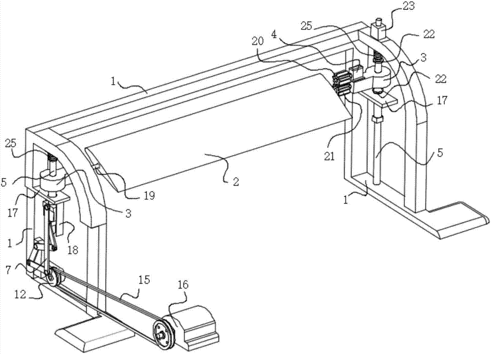
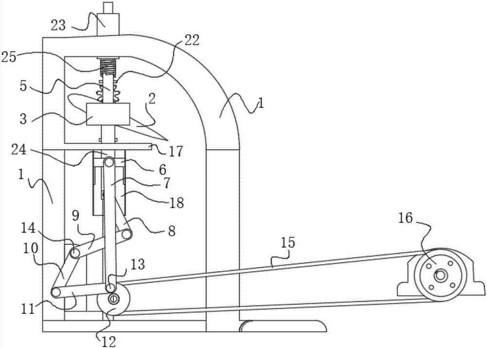
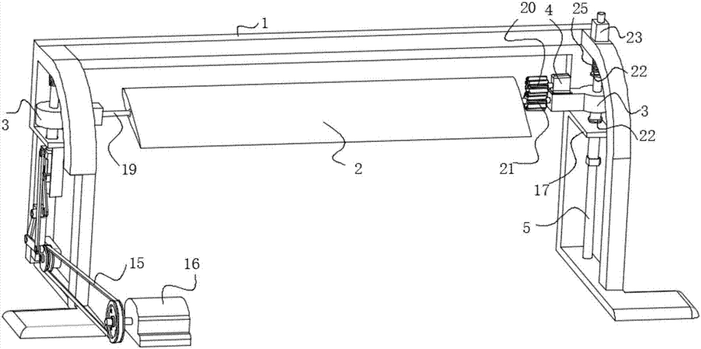
[0018] like Figure 1 to Figure 3 As shown, a reciprocating oscillation flapping wing energy conversion device inc...


PUM


Abstract

The invention discloses a reciprocating oscillation flapping energy conversion device. The device comprises a frame, a flapping wing, a dip angle adjusting device, two slide blocks, two slide columns, a connecting rod mechanism, a small belt wheel, a controller, and a power generation device; the two slide columns are respectively fixed at two ends of the frame; the two slide blocks are respectively sleeved on the two slide columns to form slide pairs; the flapping wing is connected with the two slide blocks through a flapping wing rotating shaft; the dip angle adjusting device is a servo motor connected with the flapping wing rotating shaft; limiting blocks are arranged at the middle parts of the slide columns; position inductors are respectively arranged at the tops and the middle parts of the slide columns; the slide blocks are connected with the small belt wheel through the connecting rod mechanism; the up-down sliding of the slide blocks is converted to the rotation of the small belt wheel through the connecting rod mechanism; the small belt wheel is connected with the power generation device through a belt; signals of the position inductors are all accessed into the controller; and the controller controls the flapping wing rotating shaft to rotate through the servo motor so as to change an attack angle of the flapping wing. The device is simple in structure, is high in energy conversion efficiency through transmission of the slide pairs and connecting rods, and is low in loss.

Description

technical field [0001] The invention relates to the field of wind power, and relates to an oscillating wind power generation device that converts reciprocating linear motion into rotational motion, and in particular to a reciprocating oscillating flapping wing energy conversion device. Background technique [0002] The phenomenon of oscillating flapping wings exists widely in nature and engineering practice. It has great application potential in wind energy and water flow energy harvesting and output. It reveals the energy harvesting mechanism of oscillating flapping wings and obtains methods to improve the output power and efficiency of flapping wings. For new oscillating flapping wings The development and application of flow field energy harvesting devices is very important. [0003] The slider crank mechanism can realize the conversion of linear motion into rotary motion, but there is a dead point problem in the working process. The present invention adopts a new type o...

Claims


Application Information

Patent Timeline
Patent Type & Authority Applications(China)
IPC IPC(8): F03D15/00F03D80/00F03D9/25F03D5/06
CPCF03D5/06F05B2260/403Y02E10/70
Inventor 朱建阳王钊蒋林
Owner WUHAN UNIV OF SCI & TECH
Why Eureka
Try Eureka