Take-off and landing device of rotor wing unmanned plane and take-off and landing method thereof

A technology of unmanned rotor and landing gear, which is applied in the direction of unmanned aircraft, landing gear, motor vehicles, etc., can solve the problems of rotorcraft's reduced load capacity, self-heaviness, and inability to carry equipment, etc., to avoid rigid contact and self-weight light effect

Pending Publication Date: 2017-08-18
申成利
View PDF1 Cites 2 Cited by
  • Summary
  • Abstract
  • Description
  • Claims
  • Application Information

AI Technical Summary

Problems solved by technology

However, this simple buffer device can only provide elastic force without damping force, resulting in the phenomenon of bouncing when the UAV lands. Chinese invention patent CN 104895995 B discloses a small UAV landing gear buffer. The buffer structure realizes the release of the damping force during the buffering process and reduces the bouncing phenomenon when the drone lands
However, due to the oil buffer structure used in this structure, its self-weight is relatively large, resulting in a decrease in the load-bearing capacity of the rotorcraft, and it cannot carry more equipment for flight

Method used


Image

  • Take-off and landing device of rotor wing unmanned plane and take-off and landing method thereof
  • Take-off and landing device of rotor wing unmanned plane and take-off and landing method thereof
  • Take-off and landing device of rotor wing unmanned plane and take-off and landing method thereof

Examples


Embodiment Construction

[0020] The standard parts used in the present invention can be purchased from the market, and the special-shaped parts can be customized according to the instructions and the accompanying drawings. The specific connection methods of each part adopt mature bolts, rivets, welding in the prior art , pasting and other conventional means, no longer described in detail here.

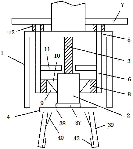
[0021] refer to Figure 1-6, a specific embodiment of the present invention includes an outer cylinder 1, an inner cylinder 2 is movably socketed in the outer cylinder 1 through a first spring body 3, a support frame 4 is connected to the bottom of the inner cylinder 2, and several rings are arranged on the top of the outer cylinder 1 Through hole 5, a first connecting rod 6 is movably inserted in the through hole 5, and the top of the first connecting rod 6 is fixedly connected with a windshield 7, and the inner side of the first connecting rod 6 is connected with a first The wedge-shaped part 9, the second ...


PUM


Abstract

The invention discloses a take-off and landing device of a rotor wing unmanned plane. The device comprises an outer cylinder, wherein the outer cylinder is movably connected with an inner cylinder through a first spring body in a sleeving mode, a support frame is connected to the bottom of the inner cylinder, a plurality of through holes are formed in the top of the outer cylinder in an annular configuration, first connecting rods are movably inserted in the through holes, a wind board is fixedly connected to the tops of the first connecting rods, first wedge shape parts are connected to the inner sides of the first connecting rods through first elastic expansion and contraction bodies, second wedge shape parts which are in selective contact with the first wedge shape parts are fixed to the outside of the inner cylinder, spacing boards which are in selective contact with the top of the inner cylinder are fixed to the inner sides of the first connecting rods, a second elastic expansion and contraction bodies are connected to the outer sides of the first connecting rods in a sleeving mode, and two ends of the second elastic expansion and contraction bodies are connected with the wind board and the outer cylinder respectively. The invention further discloses a take-off and landing method of the take-off and landing device of the rotor wing unmanned plane. According to the device, the shortage of the prior art can be improved, an oil liquid buffering structure is not used, and the self-weight of the rotor wing unmanned plane is further lowered.

Description

technical field [0001] The invention relates to the technical field of unmanned aerial vehicles with rotors, in particular to a landing device and a landing method for unmanned aerial vehicles with rotors. Background technique [0002] Rotor UAVs have been widely used in recent years due to their flexible flight and ability to hover. In order to ensure the stability and safety of the rotor UAV during landing, the landing gear needs to be specially designed. The simple landing gear is to add springs to buffer the landing impact. However, this simple buffer device can only provide elastic force without damping force, resulting in a bouncing phenomenon when the UAV lands. Chinese invention patent CN 104895995 B discloses a small UAV landing gear buffer, through the design of oil The buffer structure realizes the release of the damping force during the buffering process and reduces the bouncing phenomenon when the drone lands. However, due to the oil buffer structure used in ...

Claims


Application Information

Patent Timeline
Patent Type & Authority Applications(China)
IPC IPC(8): B64C25/62
CPCB64C25/62B64U10/10Y02T50/40
Inventor 申成利
Owner 申成利
Why Eureka
Try Eureka