
Automatic clamping machine

A technology of automatic clamping and clamping mechanism, applied in clamping, workpiece clamping device, metal processing machine parts, etc. Simple structure, easy pre-adjustment, accurate positioning effect

Active Publication Date: 2019-02-19
NANTONG HAILITE RUBBER & PLASTIC MACHINERY
View PDF7 Cites 0 Cited by
  • Summary
  • Abstract
  • Description
  • Claims
  • Application Information

AI Technical Summary

Problems solved by technology

[0002] In the field of mechanical manufacturing, in the process of workpiece processing and manufacturing, it is often necessary to clamp the workpiece to be processed before reprocessing. The existing rotary table clamps are used for clamping operations for small parts, but for larger workpieces Generally speaking, the use of fixtures will be limited, and the existing clamping effect is not good enough for the processing of larger workpieces, and flexible clamping adjustments cannot be made according to the size of the processed workpieces, resulting in limited use of clamping equipment. In addition, the existing clamping operation structure is relatively complicated, the cost is high, and the workpiece may shake on one side after clamping, which will affect the machining accuracy and quality of the workpiece during the processing

Method used


Image

  • Automatic clamping machine
  • Automatic clamping machine
  • Automatic clamping machine

Examples


Embodiment Construction

[0022] In order to enable those skilled in the art to better understand the technical solution of the present invention, the technical solution of the present invention will be further described below in conjunction with the accompanying drawings and embodiments.

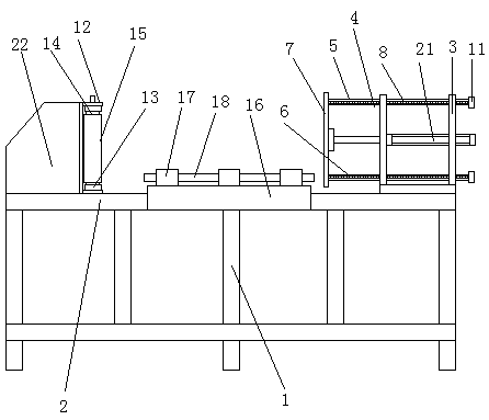
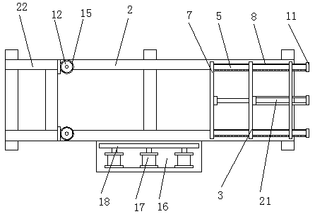
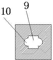
[0023] Refer to attached Figure 1-4 The automatic clamping machine shown includes a frame 1, on which a base 2 composed of two parallel beams is set, one end of the base 2 is set with a fixed clamping mechanism, and the other end is set with a movable clamping mechanism. Clamping mechanism, the movable clamping mechanism includes a square fixed frame 3 and a moving frame 4, the moving frame 4 is slidably connected with the square fixed frame 3, and the square fixed frame 3 and the moving frame 4 A hydraulic pushing mechanism is provided, and the mobile frame 4 moves horizontally on the square fixed frame 3. The hydraulic pushing mechanism is a hydraulic cylinder 21, and the hydraulic cylinder 21 is controlled by a ...


PUM


Abstract

The invention discloses an automatic clamping machine comprising a rack. A base composed of two mutually-parallel cross beams is arranged on the rack; a fixed type clamping mechanism is arranged at one end of the base, and a movable type clamping mechanism is arranged at the other end of the base; the movable type clamping mechanism comprises a square fixed frame and a movable frame, wherein the movable frame is slidably connected with the square fixed frame; a hydraulic pushing mechanism is arranged between the square fixed frame and the movable frame, and the movable frame horizontally moves on the square fixed frame; and a locating clamping mechanism is further arranged on one side face of the base. The automatic clamping machine is simple in structure, convenient to operate and high in clamping flexibility, pre-adjustment according to different workpiece dimensions is facilitated, and all the surfaces of a clamped workpiece can maintain high stability.

Description

technical field [0001] The invention relates to an automatic clamping machine. Background technique [0002] In the field of machinery manufacturing, in the process of workpiece processing and manufacturing, it is often necessary to clamp the workpiece to be processed before reprocessing. The existing rotary table clamps are used for clamping operations for small parts, but for larger workpieces Generally speaking, the use of fixtures will be limited, and the existing clamping effect is not good enough for the processing of larger workpieces, and flexible clamping adjustments cannot be made according to the size of the processed workpieces, resulting in limited use of clamping equipment. Limitations. In addition, the existing clamping operation structure is relatively complicated and the cost is high. After clamping, the workpiece may shake on one side, which will affect the machining accuracy and quality of the workpiece during the machining process. Contents of the inven...

Claims


Application Information

Patent Timeline
Patent Type & Authority Patents(China)
IPC IPC(8): B25B11/00B23Q3/00
CPCB23Q3/00B25B11/00
Inventor 储绍清
Owner NANTONG HAILITE RUBBER & PLASTIC MACHINERY
Learn More