
An orthopedic drilling fixation device

A fixation device and orthopedic technology, applied in the direction of bone drill guidance, medical science, surgery, etc., can solve the problems of large incision space, large volume of bone forceps, troublesome use, etc., to achieve high convenience, small structure, and avoid injury Effect

Active Publication Date: 2020-05-05
李冰冰
View PDF7 Cites 0 Cited by
  • Summary
  • Abstract
  • Description
  • Claims
  • Application Information

AI Technical Summary

Problems solved by technology

[0002] Human extremity fractures are one of the most common clinical manifestations of orthopedic trauma. Internal fixation of fractures is a comprehensive treatment based on restoration of anatomical relationship, stable fixation, preservation of bone blood supply and early functional activities as much as possible. In the prior art, screw fixation and reduction are often used when the limbs are fractured. During the operation, the fixation device is used to fix the hole, and then the screw is used for reduction and fixation. However, most of the existing fixation devices are bone clamps, but the bone clamp It is large in size and occupies a large incision space, so it will not only affect the subsequent drilling operation and screw insertion operation, but also require a large periosteum stripping range, which will affect the blood supply to the fracture. In addition, clinically, it often needs to be fixed and reset as needed. It is troublesome to use clamps with different inner diameters for different bone thicknesses.

Method used


Image

  • An orthopedic drilling fixation device
  • An orthopedic drilling fixation device

Examples


Embodiment Construction

[0013] The following will clearly and completely describe the technical solutions in the embodiments of the present invention with reference to the accompanying drawings in the embodiments of the present invention. Obviously, the described embodiments are only some, not all, embodiments of the present invention. Based on the embodiments of the present invention, all other embodiments obtained by persons of ordinary skill in the art without making creative efforts belong to the protection scope of the present invention.

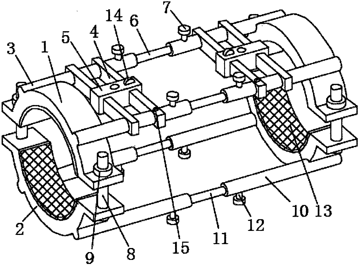
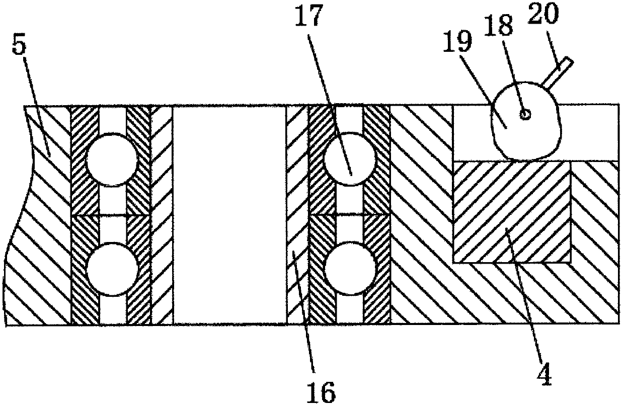
[0014] see Figure 1-2 , the present invention provides a technical solution: an orthopedic drilling fixation device, comprising an upper fixation ring 1 and a lower fixation ring 2, the upper fixation ring 1 and the lower fixation ring 2 are semicircular, and the upper fixation ring 1 and the lower fixation ring The number of 2 is two and their central axes coincide. The upper fixing ring 1 and the lower fixing ring 2 on the left and right sides cooperate wit...


PUM


Abstract

The invention discloses an orthopedics drilling fixation device. The device comprises upper fixation rings and lower fixation rings, wherein the upper fixation rings and the lower fixation rings are both of a semicircular shape, the number of the upper fixation rings and the lower fixation rings are both two, and middle axes of the upper fixation rings and the lower fixation rings are coincident; protrusion blocks are arranged on the edges of the upper fixation rings and the lower fixation rings, through holes are formed in the protrusion blocks, the upper fixation rings and the lower fixation rings are connected through screws which are arranged in the through holes, and nuts are arranged on the outer portions of the screws in a sleeving mode; the orthopedics drilling fixation device is relatively small and exquisite in structure, the occupied incision space is not large, large-scale periosteum stripping on patients can be avoided, the blood supply on fractures cannot be influenced, and subsequent drilling operation and screwing operation cannot be influenced; the orthopedics drilling fixation device can further adjust different fixation inner diameters according to different thicknesses of bones which need fixation and restoration, is high in convenience degree and applicability and further provided with a drilling aiming device, and avoids the harm for the patients caused by wrong positions during drilling.

Description

technical field [0001] The invention relates to the technical field of medical devices, in particular to an orthopedic drilling fixation device. Background technique [0002] Human extremity fractures are one of the most common clinical manifestations of orthopedic trauma. Internal fixation of fractures is a comprehensive treatment based on restoration of anatomical relationship, stable fixation, preservation of bone blood supply and early functional activities as much as possible. In the prior art, screw fixation and reduction are often used when the limbs are fractured. During the operation, the fixation device is used to fix the hole, and then the screw is used for reduction and fixation. However, most of the existing fixation devices are bone clamps, but the bone clamp It is large in size and occupies a large incision space, so it will not only affect the subsequent drilling operation and screw insertion operation, but also require a large periosteum stripping range, whi...

Claims


Application Information

Patent Timeline
Patent Type & Authority Patents(China)
IPC IPC(8): A61B17/16A61B17/17
CPCA61B17/162A61B17/17
Inventor 李冰冰
Owner 李冰冰
Learn More