A special-shaped anti-skid pre-twisted wire

A pre-twisted, special-shaped technology, applied in the field of special-shaped anti-slip pre-twisted wires, can solve the problems of inconvenient installation and construction, abrasion of wires, easy wear, etc., and achieve the effects of simple construction, increased friction, and convenient portability

Active Publication Date: 2019-03-12
YUNNAN POWER GRID CO LTD ELECTRIC POWER RES INST
View PDF12 Cites 0 Cited by
  • Summary
  • Abstract
  • Description
  • Claims
  • Application Information

AI Technical Summary

Problems solved by technology

[0005] The invention provides a special-shaped non-slip pre-twisted wire to solve the problems that the existing pre-twisted wire is easy to wear and damage the wire, and the installation and construction are inconvenient and the cost is high.

Method used


Image

  • A special-shaped anti-skid pre-twisted wire
  • A special-shaped anti-skid pre-twisted wire
  • A special-shaped anti-skid pre-twisted wire

Examples


Embodiment 1

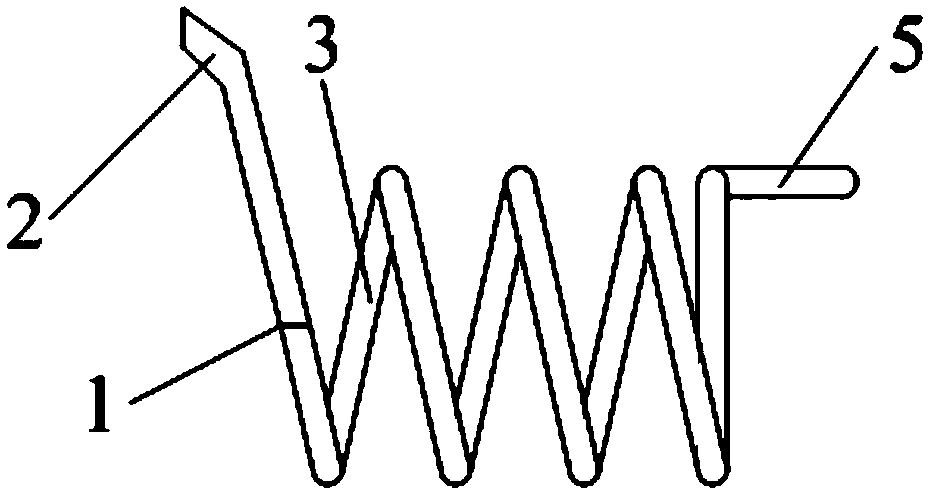
[0028] see figure 1 , is a schematic diagram of the structure of the special-shaped non-slip pre-twisted wire provided in Embodiment 1 of the present invention.

[0029] The special-shaped non-slip pre-twisted wire provided by the embodiment of the present invention includes: a pre-twisted wire body 1, a support end 2, a parallel tail end 5 and an anti-skid layer 3, wherein,

[0030] The pre-twisted wire body 1 is helical, and one end of the pre-twisted wire body 1 is higher than the radial height of the pre-twisted wire body 1;

[0031] Specifically, the overall size of the pre-twisted wire provided in this embodiment is equivalent to half of the size of the existing pre-twisted wire, and on the basis of the existing pre-twisted wire structure, one end of the pre-twisted wire body 1 is increased to make One end of the pre-twisted wire body 1 is obviously higher than the radial height of the pre-twisted wire body 1 . The increased section of the pre-twisted wire body 1 can e...

Embodiment 2

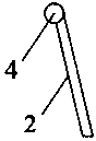
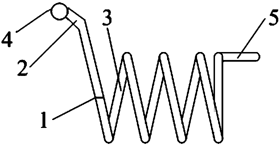
[0044] see figure 2 and image 3 , figure 2 A schematic diagram of the structure of the special-shaped wire anti-vibration hammer anti-slip pre-twisted wire provided by Embodiment 2 of the present invention, image 3 An enlarged view of a solid bead provided as an example of the present invention.

[0045] The difference between the special-shaped non-slip pre-twisted wire provided by the embodiment of the present invention and the first embodiment is that it further includes a solid ball 4 , and the solid ball 4 is arranged at the other end of the support end 2 .

[0046] The purpose of setting the solid ball 4 can better realize the contact between the pre-twisted wire and the outer edge of the anti-vibration hammer, and block the outer surface of the anti-vibration hammer without damaging the wire.

[0047] Optionally, the diameter of the solid ball 4 is 3mm-5mm. The diameter of the solid ball 4 need not be too large, so as to block the anti-vibration hammer.

[0048...


PUM


Abstract

The invention discloses a specially-shaped anti-skid pre-twisted wire comprising a pre-twisted wire body, a support end, a parallel tail and an anti-skid layer. The pre-twisted wire body is in a spiral shape; and one end of the pre-twisted wire body increases. One end of the support end is angularly connected to one end of the pre-twisted body. The parallel tail is arranged at the other end of the pre-twisted body and the axis of the parallel end is parallel to the axis of the pre-twisted body. The anti-skid layer is arranged at the surfaces of the pre-twisted body, the support end and the parallel end respectively. The pre-twisted wire is used for fixing a damper of a power transmission and distribution line. With the support end, the parallel tail and the anti-skid layer, the damper lead can be clamped, the contact area with the lead can be increased, and thus the friction force can be enhanced, so that lead wearing caused by sliding of the damper can be avoided. Moreover, the pre-twisted wire employs two-end-plugged mounting method, so that the construction becomes simple and the damping and anti-oscillating effects of the damper are good. The pre-twisted wire has advantages of small size, high portability, and low cost.

Description

technical field [0001] The invention relates to the technical field of installation of electric power fittings, in particular to a special-shaped anti-slip pre-twisted wire. Background technique [0002] Due to the high pole position and large span of high-voltage overhead lines, when the conductor is subjected to wind force, it will vibrate, and the vibration of the conductor will threaten the safe operation of the transmission line. Therefore, in order to reduce the vibration level of the conductor and ensure the safe and stable operation of the transmission line, an anti-vibration hammer is usually installed on the conductor. In order to ensure that the anti-vibration hammer is installed at the designated position without slippage, fixed equipment is usually used to fix the anti-vibration hammer, so as to prevent the anti-vibration hammer from leaving its original position and lose the anti-vibration effect. If it is not adjusted in time, the wire will be worn for a long ...

Claims


Application Information

Patent Timeline
Patent Type & Authority Patents(China)
IPC IPC(8): H02G7/14
CPCH02G7/14
Inventor 李国彬申元周仿荣韩凌云伍鸿飞邹德旭程志万潘浩
Owner YUNNAN POWER GRID CO LTD ELECTRIC POWER RES INST
Why Eureka
Try Eureka