
A steel pipe rolling device

A technology of steel pipe and speed change device, which is applied in the direction of rolling mill control device, metal rolling, metal rolling, etc. It can solve the problems of low work efficiency, long time spent, and incapable of automatic operation, so as to improve work efficiency and uniform force , The effect of ensuring accuracy

Active Publication Date: 2019-04-16
张家港市宏大钢管有限公司
View PDF8 Cites 1 Cited by
  • Summary
  • Abstract
  • Description
  • Claims
  • Application Information

AI Technical Summary

Problems solved by technology

[0004] The technical problem to be solved by the present invention is that the existing steel pipe rolling device cannot operate automatically, takes a long time, and has low work efficiency. A new steel pipe rolling device is provided

Method used


Image

  • A steel pipe rolling device
  • A steel pipe rolling device

Examples


Embodiment Construction

[0032] In order to make the object, technical solution and advantages of the present invention more clear, the present invention will be further described in detail below in conjunction with the examples. It should be understood that the specific embodiments described here are only used to explain the present invention, not to limit the present invention.

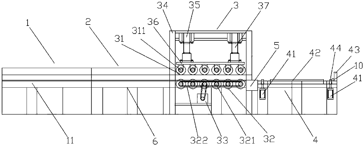
[0033] like figure 1 , 2 As shown, Wood invented a steel pipe rolling device, including a support 6, and the support 6 is provided with an automatic feeding mechanism 1, a rotary feeding mechanism 2, a billet rolling mechanism 3, and an automatic unloading device connected in sequence. 4 and a controller 5 for controlling the above-mentioned devices to work.

[0034] The rotary feeding mechanism 2 includes a feeding transmission mechanism that drives the feeding trolley 22 to move through at least one lead screw 21 and a rotary transmission mechanism that drives the polished rod 23 and the chuck 24 to rotate. The feeding...


PUM


Abstract

The invention relates to a steel tube rolling device, and mainly solves the problem that an existing steel tube rolling device cannot operate automatically and is low in working efficiency. According to the technical scheme, the steel tube rolling device comprises a support, wherein an automatic feeding mechanism, a rotation feeding mechanism, a tube blank rolling mechanism, an automatic discharging mechanism and a controller which are successively connected are arranged on the support; and the controller is used for controlling the automatic feeding mechanism, the rotation feeding mechanism, the tube blank rolling mechanism and the automatic discharging mechanism to work. The problem is solved well. The steel tube rolling device is easily used industrially.

Description

technical field [0001] The invention relates to a steel pipe rolling device. Background technique [0002] In daily life, steel pipes have become more and more important as a daily necessities. Whether it is in common mechanical parts or in the construction industry, steel pipes can be seen even in daily decoration. Therefore, the steel pipe Quality will attract more and more people's attention. At present, the steel pipe rolling process is usually manual operation or manual loading and unloading. The processing efficiency is low, which will increase the working time and seriously affect the work efficiency. [0003] Another example is that the Chinese patent document CN 204817481U discloses a steel pipe rolling device, including a bracket, a moving frame, a connecting rod, and a track. The bracket is provided with a slot, and a block is installed in the slot, and a nut is passed on the block. It is connected with the swing rod. There is a fixed chuck on the top of the brac...

Claims


Application Information

Patent Timeline
Patent Type & Authority Patents(China)
IPC IPC(8): B21B21/04B21B17/00B21B37/78B21B39/00
CPCB21B17/00B21B21/04B21B37/78B21B39/00
Inventor 王忠华朱剑峰仲蔡希
Owner 张家港市宏大钢管有限公司
Learn More