Eureka AIR delivers breakthrough ideas for toughest innovation challenges, trusted by R&D personnel around the world.

Test and Test Jitter Platform and Its Jitter Method

A jitter platform and testing technology, applied in the field of detection, can solve the problems of large jitter amplitude and inability to meet the requirements of "anti-shake" detection, and achieve the effect of reducing offset, improving precision and improving accuracy

Active Publication Date: 2019-01-08
GUANGZHOU INST OF MEASURING & TESTING TECH
View PDF7 Cites 0 Cited by
  • Summary
  • Abstract
  • Description
  • Claims
  • Application Information

AI Technical Summary

Problems solved by technology

At present, there is no such ready-made equipment on the market, and the existing equipment has a large vibration range, which cannot meet the requirements of "anti-shake" detection

Method used


Image

  • Test and Test Jitter Platform and Its Jitter Method
  • Test and Test Jitter Platform and Its Jitter Method
  • Test and Test Jitter Platform and Its Jitter Method

Examples


Embodiment 1

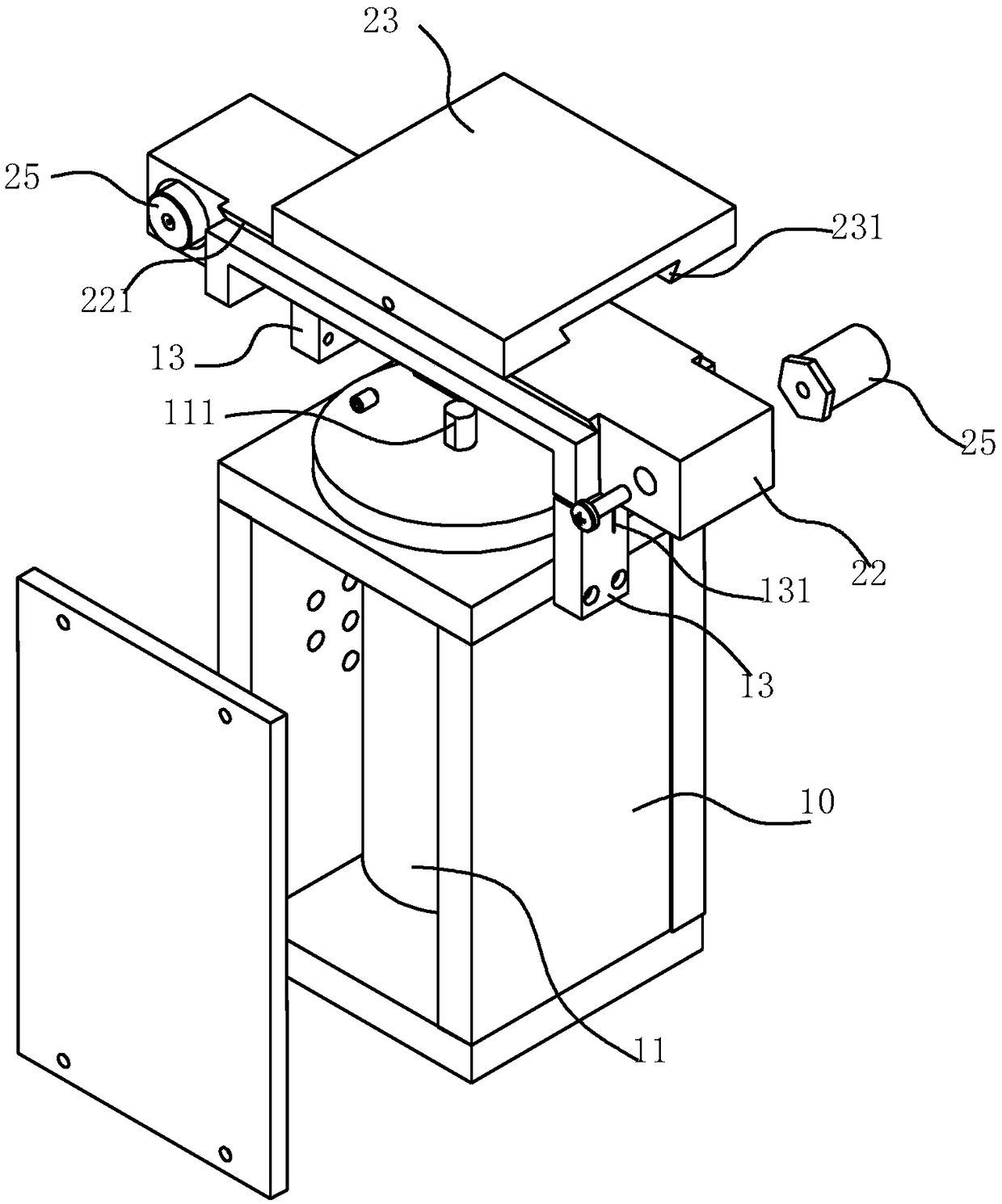
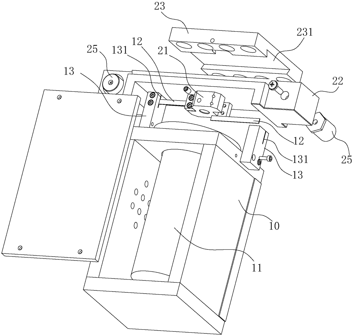
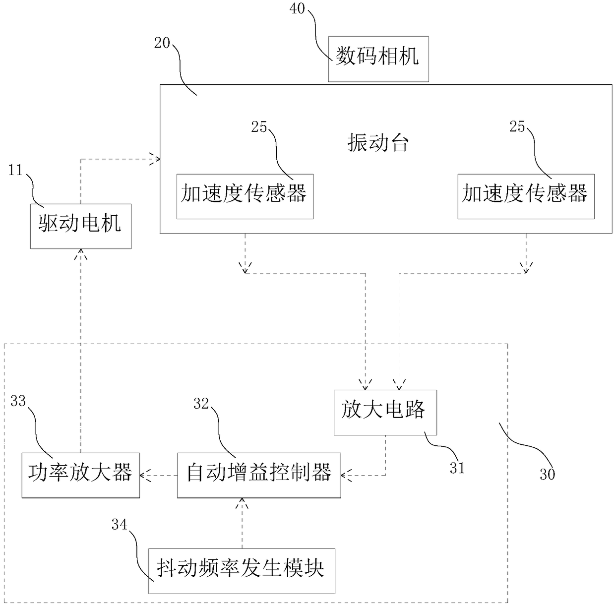
[0039] like figure 1 , figure 2 and image 3As shown, the detection test shake platform is used to test the anti-shake performance of the digital camera 40. It includes a body 10 and a vibration table 20. The body 10 is provided with a drive motor 11 and a drive motor 11 Electrically connected with the control circuit 30, the drive motor 11 has a vibrating output shaft 111 facing upwards, and a shaft coupling 21 is provided below the vibrating table 20, and the coupling 21 is connected to the upper end of the vibrating output shaft 111. The vibrating table 20 Located above the vibration output shaft 111 , an elastic vibration limiting member 12 is provided between the body 10 and the vibrating table 20 .

[0040] Wherein, the shaking limiting member 12 is an elastic metal strip, and there are two shaking limiting members 12 located on two opposite sides of the coupling 21 . The fuselage 10 is provided with a limit column 13, and the limit column 13 is provided with a limit...

Embodiment 2

[0055] like Figure 4 , Figure 5 As shown, in this embodiment, the vibrating table 20 further includes a side table 24 , one side of the side table 24 is connected to one side of the fixed table 23 . One side of the side platform 24 is connected to one side of the fixing platform 23, and the digital camera 40 can be installed and fixed as required to meet different installation or detection requirements.


PUM


Abstract

The invention discloses a detection test jittering platform and a jittering method thereof. The detection test jittering platform comprises a machine body and a vibrating table; a driving motor is arranged on the machine body; the driving motor is electrically connected with a control circuit; the driving motor is provided with a jittering output shaft upwards; a coupler is arranged below the vibrating table; the coupler is connected with the upper end of the jittering output shaft; the vibrating table is positioned above the jittering output shaft; and an elastic jittering limiting part is arranged between the machine body and the vibrating table. The invention can provide the jittering platform which aims at anti-jittering performance detection and is more accurate in control of vibration amplitude, and is very important for improving experiment or detection accuracy and reducing detection cost.

Description

technical field [0001] The invention belongs to the field of detection, and in particular relates to a vibration detection platform for a test test and a method for detecting the vibration of a test vibration platform. Background technique [0002] With the continuous improvement of people's living standards in our country, digital cameras have gradually entered thousands of households. From 2000 to 2008, the sales volume of digital cameras in my country has increased at an annual rate of more than 50%, accounting for 10% of the world's digital camera sales. The resulting complaints about the quality of such products are also on the rise. Statistics from the Shanghai 12365 Complaint and Reporting Center show that complaints about digital cameras mainly focus on crashes, red-eye problems, unclear imaging, incorrect exposure in automatic mode, and insufficient charging. In order to standardize the market, improve quality, promote the healthy development of enterprises, and pr...

Claims


Application Information

Patent Timeline
Patent Type & Authority Patents(China)
IPC IPC(8): H04N17/00
CPCH04N17/002
Inventor 谭山王潇潇黄锋
Owner GUANGZHOU INST OF MEASURING & TESTING TECH
Why Eureka
Eureka Blog
Learn More