Drive Apparatus, Drive Method, And Optical Device
A driving device and optical equipment technology, applied in optics, projection devices, printing devices, etc., can solve the problems of high frequency, high power consumption, abnormal noise, etc., and achieve the effect of suppressing abnormal noise and reducing power consumption
- Summary
- Abstract
- Description
- Claims
- Application Information
AI Technical Summary
Problems solved by technology
Method used
Image
Examples
no. 1 approach
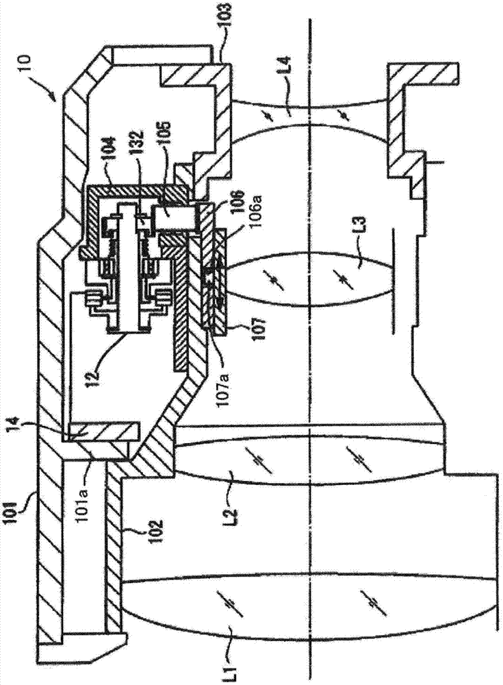
[0082] figure 1 It is a schematic diagram which shows the structure of the lens barrel of 1st Embodiment of this invention. The lens barrel 10 is a lens barrel for an imaging device such as a digital camera. The lens barrel 10 has an outer fixed barrel 101 , a first inner fixed barrel 102 and a second inner fixed barrel 103 . The outer fixing barrel 101 covers the outer peripheral portion of the lens barrel 10 . The first inner fixed cylinder 102 and the second inner fixed cylinder 103 exist on the inner peripheral side of the outer fixed cylinder 101 , the first inner fixed cylinder 102 is located on the subject side, and the second inner fixed cylinder 103 is located on the image side.
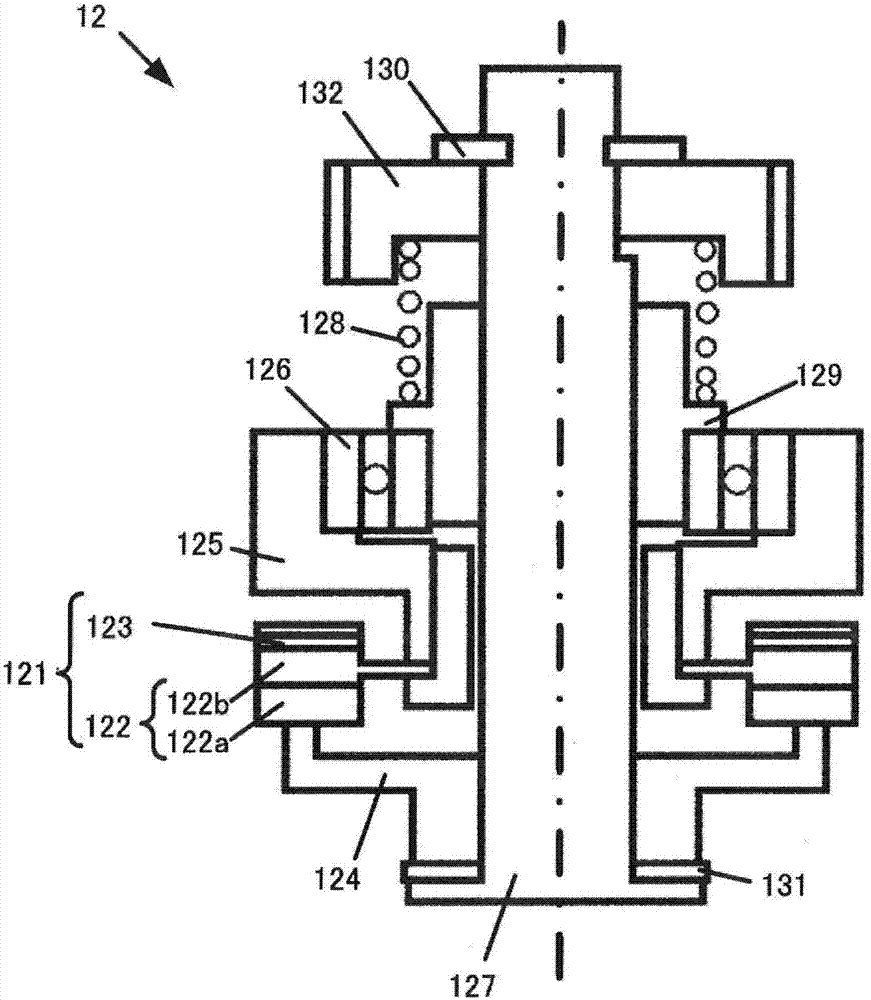
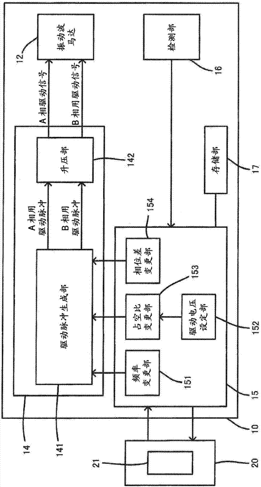
[0083] Between the outer fixed cylinder 101 and the first inner fixed cylinder 102 , a vibration wave motor (vibration actuator) 12 , a driving device 14 and a gear unit module 104 are arranged and fixed on the first inner fixed cylinder 102 . The gear unit module 104 has a reduction gear...
no. 2 approach
[0129] A second embodiment of the present invention will be described. In the second embodiment, before changing the phase difference, not only the driving voltage is lowered, but also the changing speed of the phase difference is set to be low (the changing speed is slowed down), thereby reducing abnormal noise when the phase difference is changed.
[0130] The range of possible values of the duty ratio of the drive pulse of each phase is limited by the resolution of PWM or the like. For example, the duty ratio of the driving pulse is assigned a set value of 0 to 255, and the set value of the duty ratio cannot be set to a value between "0" and "1". The lower limit of the set value of V1 is determined, for example, by the product of the duty ratio d1 corresponding to the set value "1" and the maximum voltage VMAX of the drive signal.
[0131] The value of VMAX varies depending on the circuit configuration of the drive device of the vibration wave motor 12, the ambient tempe...
Deformed example 1
[0151] In the first embodiment, in the lens-side MCU 15 , the duty ratio changing unit 153 changes the set value of the duty ratio in the drive pulse generating unit 141 . However, the lens-side MCU 15 may include a power supply voltage changing unit 35 - 3 instead of the duty ratio changing unit 153 . In addition, in the second embodiment, in the lens-side MCU 35 , the power supply voltage changing unit 35 - 3 changes the power supply voltage of the booster unit 142 . However, the lens-side MCU 35 may include a duty ratio changing unit 153 instead of the power supply voltage changing unit 35-3.
PUM
 Abstract
Description
Claims
Application Information
 - R&D
- Intellectual Property
- Life Sciences
- Materials
- Tech Scout
- Unparalleled Data Quality
- Higher Quality Content
- 60% Fewer Hallucinations
Browse by: Latest US Patents, China's latest patents, Technical Efficacy Thesaurus, Application Domain, Technology Topic, Popular Technical Reports.
© 2025 PatSnap. All rights reserved.Legal|Privacy policy|Modern Slavery Act Transparency Statement|Sitemap|About US| Contact US: help@patsnap.com


