An automatic cancellation device for induction logging direct coupling signal

An induction logging and cancellation device technology, applied in the field of electromagnetic induction, can solve the problems of poor stability, insufficient coil precision, large time consumption and labor costs, etc., and achieve the effects of high reliability, increased accuracy and strong adaptability

Active Publication Date: 2018-12-18
UNIV OF ELECTRONICS SCI & TECH OF CHINA
View PDF7 Cites 0 Cited by
  • Summary
  • Abstract
  • Description
  • Claims
  • Application Information

AI Technical Summary

Problems solved by technology

However, the wound coil has the disadvantages of insufficient precision and poor stability, and once the assembly is completed, if the cancellation effect of the instrument changes during transportation and use, or the cancellation error occurs due to changes in the use environment, the cancellation must be re-adjusted , which will consume a lot of time and labor costs

Method used


Image

  • An automatic cancellation device for induction logging direct coupling signal
  • An automatic cancellation device for induction logging direct coupling signal
  • An automatic cancellation device for induction logging direct coupling signal

Examples


Embodiment 1

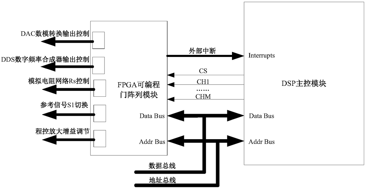
[0042] An embodiment of the present invention provides an automatic cancellation device for induction logging direct coupling signals, such as figure 1 As shown, it includes an addition operation circuit module 10 , a signal amplification filter conditioning module 3 , an ADC sampling module 4 , an FPGA programmable gate array module 5 , a phase compensation signal output module 6 , and a gain adjustment control module 7 connected in sequence. The input terminals of the addition operation circuit module 10 are respectively connected with the receiving coil 2 of the induction logging tool and the output terminals of the gain adjustment control module 7 .

[0043] The addition operation circuit module 10 is used to superimpose the mixed signal S5 received by the receiving coil 2 of the induction logging tool and the compensation signal S4 generated by the phase compensation signal output module to form a composite signal S6; the mixed signal S5 is received by the receiving coil 2...

Embodiment 2

[0056] The embodiment of the present invention provides a method for automatic cancellation of induction logging direct coupling signals, such as image 3 shown, including the following steps:

[0057] A1. Select a transmitting coil of the induction logging tool to enable the output of the transmitting signal to the formation, and notify the FPGA programmable gate array module to control the reference signal switching module to switch to the corresponding transmitting coil channel.

[0058] Before proceeding to step A1, necessary conventional preprocessing operations are required, including powering on and initializing the DSP main control module and FPGA programmable gate array module, and controlling the DSP main control module to wait in the main function to start sending work instructions, etc.

[0059] A2. Control the receiving coil of the induction logging tool to receive the direct coupling signal from the transmitting coil and the secondary induction signal from the fo...


PUM


Abstract

The invention discloses an automatic cancellation device for induction well logging direct coupling signals, which implements the cancellation of direct coupling signals by means of internal feedback compensation and cancellation in a signal processing circuit. The present invention realizes the orthogonal separation of the received composite signal through the digital phase-sensitive detection technology DPSD, and according to the magnitude and phase correspondence of the real part and the imaginary part, the FPGA programmable gate array module controls the DDS digital frequency synthesizer to output one and the reference signal The reverse compensation signal with similar amplitude is superimposed with the composite signal, and the direct coupling signal and the feedback compensation signal are subtracted to cancel each other out, and finally the remaining secondary induction signal is extracted to participate in the conversion of the final conductivity. The method automatically realizes the cancellation of the direct coupling signal through a software algorithm, saves the hardware structure of the compensation coil, does not need to be calibrated, has strong practicability and better reliability.

Description

technical field [0001] The invention belongs to the technical field of electromagnetic induction, and in particular relates to the design of an automatic cancellation device for induction logging direct coupling signals. Background technique [0002] The transmitting coil of the induction logging tool generates eddy current in the conductive formation, and the eddy current generates a secondary induction signal carrying formation information to the receiving coil, and the formation information is obtained by measuring the secondary induction signal. However, in the actual measurement process, due to the coupling effect between the transmitting coil and the receiving coil, the receiving coil will also receive the direct coupling signal from the transmitting coil. The direct coupling signal does not carry formation information, and is usually a useless signal, and is generally several orders of magnitude larger than the secondary induction signal. If it is not canceled, the us...

Claims


Application Information

Patent Timeline
Patent Type & Authority Patents(China)
IPC IPC(8): G01V3/28G01V3/38
CPCG01V3/28G01V3/38
Inventor 管国云聂在平孙向阳
Owner UNIV OF ELECTRONICS SCI & TECH OF CHINA
Why Eureka
Try Eureka