Horizontal safety braking device for gear and rack driven lifting equipment

A technology of lifting equipment and safety braking, which is applied in elevators, hoisting devices, transportation and packaging, etc., and can solve problems such as performance reduction, failure, and inability to guarantee reliable braking

Active Publication Date: 2017-08-11
TIANJIN JINHANG COMP TECH RES INST
View PDF5 Cites 3 Cited by
  • Summary
  • Abstract
  • Description
  • Claims
  • Application Information

AI Technical Summary

Problems solved by technology

[0002] The safety braking measures of the existing rack and pinion lifting equipment are realized by friction braking on the motor shaft or by friction braking on the gear shaft. Friction braking may be caused by the friction material Performance reduction or failure caused by wear, oil pollution, etc.; in addition, if there is a problem with the drive gear, such as tooth damage, reliable braking cannot be guaranteed even if the gear does not rotate; to ensure safety, the rack-and-pinion lifting equipment must be equipped with reliable Safety brakes that can deal with problems involving drive gears and similar safety issues

Method used


Image

  • Horizontal safety braking device for gear and rack driven lifting equipment
  • Horizontal safety braking device for gear and rack driven lifting equipment
  • Horizontal safety braking device for gear and rack driven lifting equipment

Examples


Embodiment 1

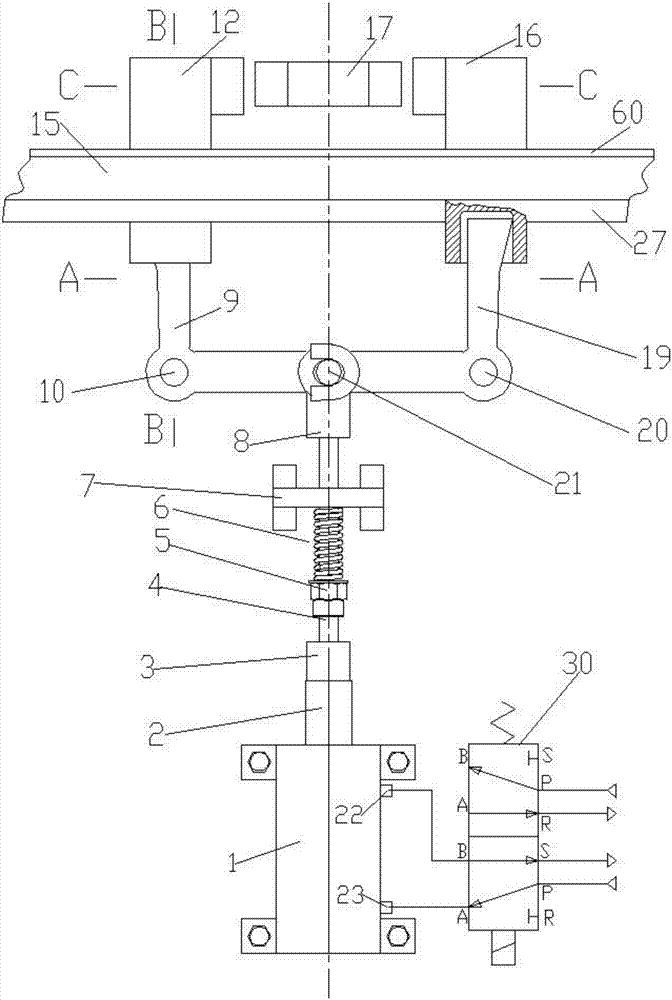
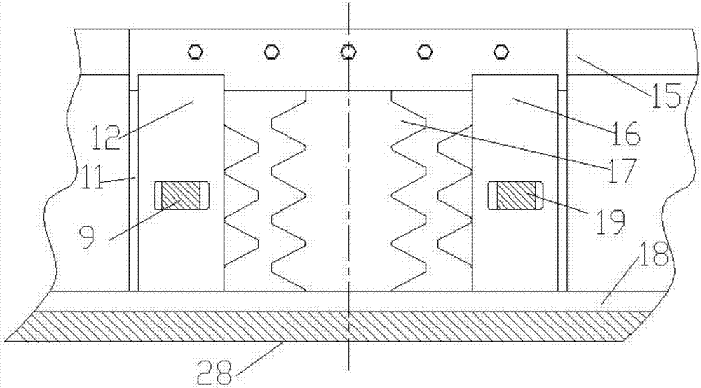
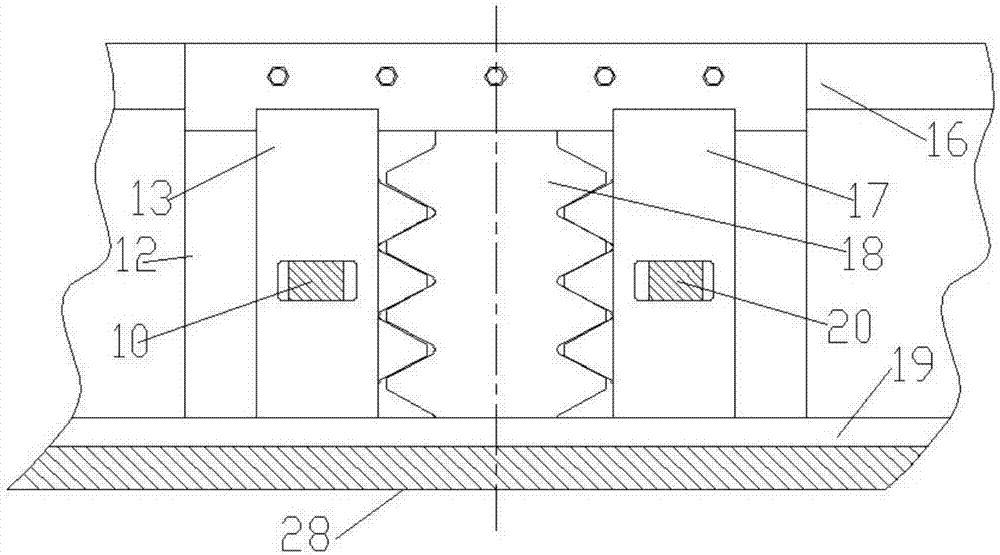
[0021] Example 1, Figure 9 It is a schematic diagram of Embodiment 1, and the drawing shows the appearance of the side of the lifting equipment. The horizontal safety brake device is installed on the top of the rack-and-pinion lifting equipment, temporarily in a free position, and the lifting equipment is ready to run or is running Case, Figure 10 It is a schematic diagram of the situation that the horizontal safety braking device of embodiment 1 brakes the lifting equipment, (the front figure 1 , figure 2 , image 3 , Figure 7 , Figure 8 The left and right mentioned are viewed from the inside of the lifting device to the side of the lifting device. Figure 9 , Figure 10 It is viewed from the outside to the side of the lifting equipment, so the left and right directions are just in reverse). Figure 1-8 , Figure 11As shown, and [0005] section, [0006] section, [0007] section, Embodiment 1 controls the compressed air or hydraulic oil through the solenoid valve to ...

Embodiment 2

[0022] Example 2, Figure 9 , Figure 10 It is also a schematic diagram of Embodiment 2, which shows an elevator equipped with a horizontal safety braking device for rack and pinion lifting equipment according to the present invention, and its appearance is the same as Figure 7 , Figure 8 , the internal structure of the horizontal safety brake device and its functions are described in Figure 1-8 , Figure 11 As shown, and described in [0005], [0006], and [0007], the working principle is the same as that described in [0021].


PUM


Abstract

The invention relates to a horizontal safety braking device for gear and rack driven lifting equipment. The horizontal safety braking device comprises a load-bearing part, a track component, movable racks, a limiting mechanism of the movable racks, a control mechanism of the movable racks, a control device of the control mechanism of the movable racks and a manual unlocking mechanism which are configured in the horizontal direction, wherein after the horizontal safety braking device enters the braking state, the tops of the movable racks are in direct contact with the main load-bearing structure of the lifting equipment cage, or in contact with the main load-bearing structure of the lifting equipment cage through a middle transition load-bearing part for load bearing; the control mechanism of the movable racks configured in the horizontal direction controls the movable racks to perform horizontal movement on the track component or remain at certain determined positions; the determined positions comprises the braking position where the movable racks are meshed with driving racks of the lifting equipment or a free position where the movable racks and the driving racks of the lifting equipment are totally separated and spaced by an interval, and the benefits of economizing the effective space, obviously improving the leveling accuracy and the safety protection braking quality are achieved.

Description

technical field [0001] The invention relates to the field of safety braking devices for lifting equipment, in particular to a horizontal safety braking device for rack and pinion lifting equipment. Background technique [0002] The safety braking measures of the existing rack and pinion lifting equipment are realized by friction braking on the motor shaft or by friction braking on the gear shaft. Friction braking may be caused by the friction material Performance reduction or failure caused by wear, oil pollution, etc.; in addition, if there is a problem with the drive gear, such as tooth damage, reliable braking cannot be guaranteed even if the gear does not rotate; to ensure safety, the rack-and-pinion lifting equipment must be equipped with reliable A safety brake that can deal with problems involving drive gears and similar safety issues. Contents of the invention [0003] The object of the present invention is to provide a reliable safety braking device capable of de...

Claims


Application Information

Patent Timeline
IPC IPC(8): B66D5/26B66B5/16
CPCB66B5/16B66D5/26
Inventor 廖忠民
Owner TIANJIN JINHANG COMP TECH RES INST
Why Eureka
Try Eureka