
Water spraying aircraft

An aircraft and water pump technology, applied in the field of aircraft, can solve the problems of high requirements for drivers and inconvenient operation, and achieve the effect of simple operation and unmanned driving

Active Publication Date: 2017-08-11
BEIHANG UNIV
View PDF5 Cites 8 Cited by
  • Summary
  • Abstract
  • Description
  • Claims
  • Application Information

AI Technical Summary

Problems solved by technology

[0005] The technical problem to be solved by the present invention is to solve the problem that the existing water-jet aircraft needs to be driven by a man, and the flight state of the aircraft needs to be adjusted according to the change of the human attitude, which has high requirements for the driver and is not easy to operate.

Method used


Image

  • Water spraying aircraft
  • Water spraying aircraft
  • Water spraying aircraft

Examples


Embodiment 1

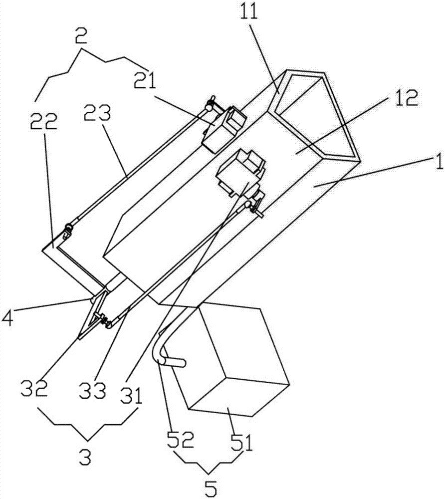
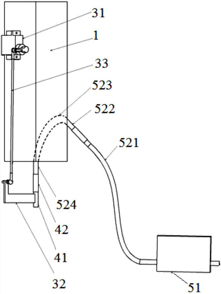
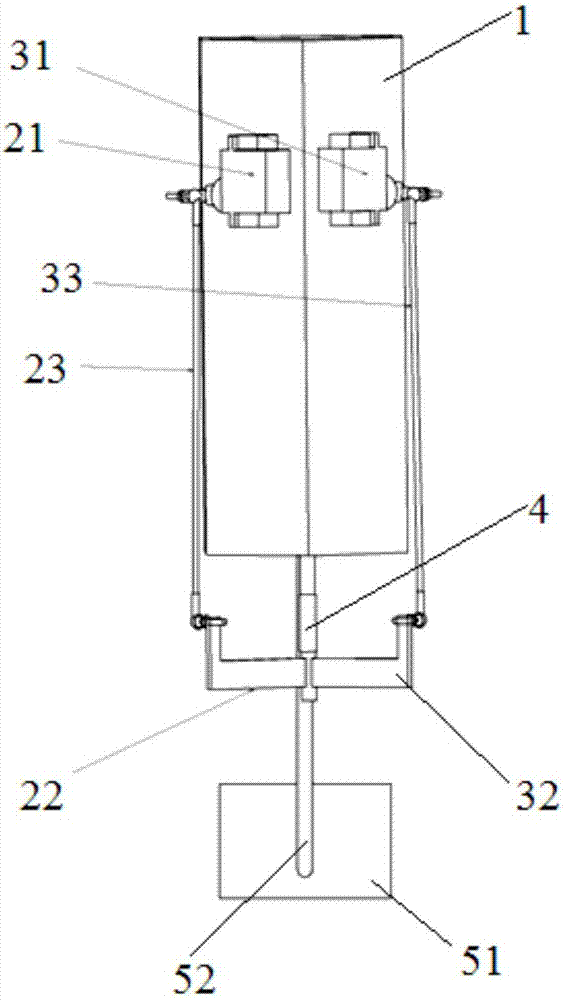
[0031] Such as Figure 1 to Figure 4 As shown, a water jet aircraft provided by the embodiment of the present invention includes an aircraft housing 1, a drive mechanism, a water supply mechanism 5 and a water spray mechanism 4, the water supply mechanism 5 is connected with the water spray mechanism 4, and the water spray mechanism 4 is deflectable Installed on the aircraft casing 1 along the vertical direction, in the present embodiment, the water spray mechanism 4 is vertically installed on the bottom of the aircraft casing 1; the drive mechanism is installed on the aircraft casing 1, and is connected with the water spray mechanism 4 , the drive mechanism includes a plurality of drive assemblies, and the plurality of drive assemblies are installed on the aircraft casing 1 and are respectively connected to a water spray mechanism 4 to provide the water spray mechanism 4 with a force in multiple directions to drive the water spray The mechanism 4 deflects in any angle. Durin...

Embodiment 2

[0044] Such as Figure 5 and Figure 6 As shown, this embodiment is similar to the solution of Embodiment 1, and the similarities between the two will not be repeated. The difference is that the number of water spraying mechanisms in this embodiment is 2, and the two water spraying mechanisms are located at The bottom of the aircraft body, the shape of the aircraft shell is a square, and the number of driving mechanisms is 2, wherein one driving mechanism includes the first driving assembly 201 and the second driving assembly 301, and the other driving mechanism includes the first driving assembly 202 And the second driving assembly 302, the water spraying mechanism 401 is driven by the first driving assembly 201 and the second driving assembly 301 arranged on two mutually perpendicular planes, and the water spraying mechanism 402 is driven by the first driving assembly arranged on two mutually perpendicular planes. Driven by the driving assembly 202 and the second driving as...


PUM


Abstract

The invention relates to the technical field of aircrafts and particularly relates to a water spraying aircraft which comprises an aircraft shell, a driving mechanism, a water supply mechanism and water spraying mechanisms, wherein the water supply mechanism is connected with the water spraying mechanisms, and the water spraying mechanisms are mounted on the aircraft shell in a deflectable way along the vertical direction; and the driving mechanism comprises a plurality of driving assemblies, and each of the driving assemblies is respectively connected with a water spraying mechanism so as to supply acting forces in multiple directions for the water spraying mechanisms. During use, the plurality of driving assemblies apply acting forces in different directions and sizes to the water spraying mechanisms, the water spraying mechanisms can deflect in different directions under the effect of multiple acting forces, the water sprayed from the water spraying mechanisms supplies a reverse thrust to an aircraft body, the magnitude of the thrust is adjusted according to the water supply quantity, the control on the flight attitude of the aircraft can be realized by virtue of the effects of the driving mechanism and the water supply mechanism, and the attitude of the aircraft does not need to be adjusted by adjusting the center of gravity according to the attitude of a person, so that unmanned driving can be realized, and the operation is simple.

Description

technical field [0001] The invention relates to the technical field of aircraft, in particular to a water jet aircraft. Background technique [0002] In the prior art of the water-jet aircraft used for entertainment performances, the autopilot technology is not used, and someone must stand or sit on the aircraft to drive it, and the remote-controlled aircraft cannot carry out unmanned independent flight. [0003] For example, the JETOVATOR developed by Jetavation Corporation of the United States is an artificially driven water jet aircraft used for entertainment. It mainly adjusts the position of the center of gravity by adjusting the position of the center of gravity and controls the direction of spraying water from the water spray mechanism on both sides to control the attitude of the aircraft to achieve flight. . This manned water-jet aircraft requires very high physical fitness and control skills of the driver, and personnel without special training cannot control it, s...

Claims


Application Information

Patent Timeline
IPC IPC(8): B64D1/18B64C39/02
CPCB64C39/024B64D1/18B64U2201/20B64U2101/00
Inventor 刘小明周浩
Owner BEIHANG UNIV
Learn More