
Semi-automatic welding fixture for sheet welding

A semi-automatic welding and thin plate welding technology, which is applied in welding equipment, auxiliary welding equipment, welding/cutting auxiliary equipment, etc., can solve the problems of inflexible welding, unsightly weld seam, and damage to human tissue, etc., and achieve good fixing effect , Fixtures are low in cost, and the effect of reducing damage

Active Publication Date: 2017-08-11
SHAANXI SCI TECH UNIV
View PDF7 Cites 4 Cited by
  • Summary
  • Abstract
  • Description
  • Claims
  • Application Information

AI Technical Summary

Problems solved by technology

[0003] At present, manual spot welding is more convenient for welding low-carbon steel thin plate parts, but if you want to obtain long and straight welds, manual welding is difficult, and the welding efficiency is low, there are many welding defects, and the welds are not beautiful. If you use a welding trolley, It is too bulky and has low applicability, and the welding cannot be flexible and changeable. Moreover, Zhang Guohong and others pointed out in "Hazards and Protection of Argon Arc Welding to the Human Body" that welding arc radiation mainly includes visible light, infrared rays and ultraviolet rays, which act on the human body. , absorbed by human tissues, causing tissue thermal action, photochemical action or ionization, causing damage to human tissue

Method used


Image

  • Semi-automatic welding fixture for sheet welding
  • Semi-automatic welding fixture for sheet welding
  • Semi-automatic welding fixture for sheet welding

Examples


Embodiment Construction

[0027] The present invention will be further described below in conjunction with the accompanying drawings and specific embodiments.

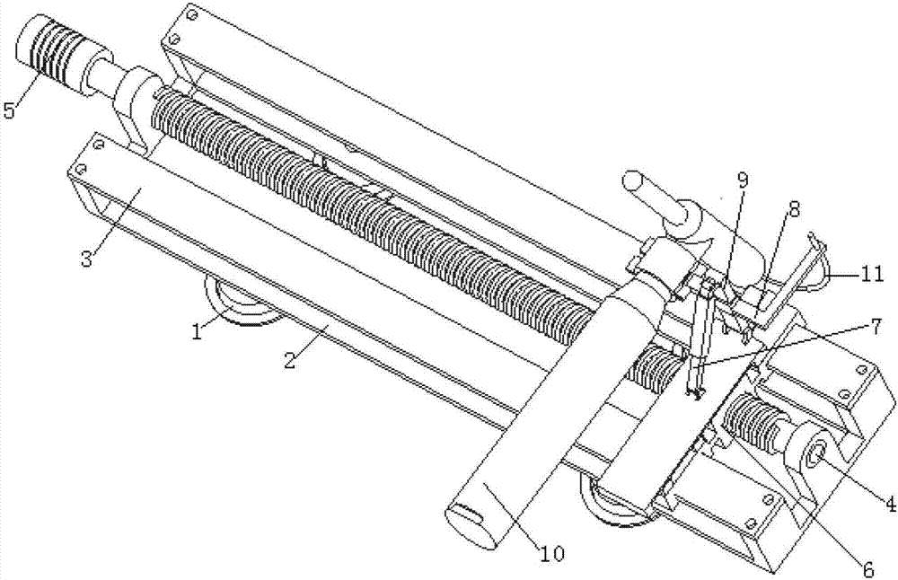
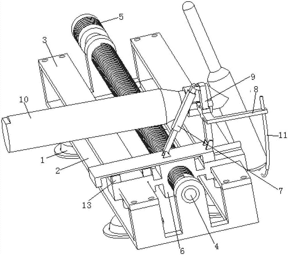
[0028] Such as figure 1 and figure 2 As shown, the present invention includes a fixture frame body 2, the top of the fixture frame body 2 is provided with a lead screw 4 and a slide rail 3 parallel to the axis of the lead screw 4, two slide rails 3 are arranged on the lead screw 4 respectively On both sides of the axial direction; the screw 4 is threaded with a nut slider 6, the end of the nut slider 6 is sleeved on the slide rail 3, and the nut slider 6 is driven by the screw 4 to slide along the slide rail 3; the nut slider A welding torch clamping device for fixing the welding torch is installed on the block 6, and the bottom of the fixture frame body 2 is provided with a fixing device fixed to the workpiece, and the fixing device is the fixture suction cup 1;

[0029] One end of the lead screw 4 is connected to the output end of the step...


PUM


Abstract

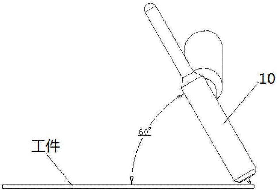
The invention discloses a semi-automatic welding fixture for sheet welding. The semi-automatic welding fixture for sheet welding comprises a fixture frame body, wherein a lead screw and a slide rail parallel to the axis of the lead screw are arranged at the top of the fixture frame body, a nut slide block is in threaded connection to the lead screw, the end part of the nut slide block is arranged on the slide rail in a sleeving manner, and the nut slide block is driven through the lead screw to slide along the slide rail; and a welding gun clamping device used for fixing a welding gun is installed on the nut slide block. The semi-automatic welding fixture for sheet welding is light in weight, capable of being adsorbed onto a weldment, and applicable to semi-automatic welding for a straight welding joint; the fixture is capable of conveniently moving and is moved after one section is welded, and then the next section is welded, so that the long and straight welding joint can be welded; the height and the angle of the welding gun can be randomly adjusted; and a welding tractor is simulated to complete welding in combination with a wire feeding mechanism.

Description

technical field [0001] The invention belongs to the technical field of welding fixtures, in particular to a semi-automatic welding fixture for thin plate welding. Background technique [0002] Because of its special properties, low-carbon steel sheet parts have a wide range of uses in life. The research on the optimization of its welding process has far-reaching significance, but the summary of the existing welding process is uneven in technology, or it is high-end. Robotic automatic welding, or manual welding, low-cost welding fixtures are less used, and people's technology and cost investment are in an awkward situation; when welding low-carbon steel sheets or thin-plate parts, deformation defects are the most difficult to control, and the metal after welding must be It will warp due to thermal expansion and contraction. After welding, the flat plate can be pressed under the iron block and cooled rapidly to prevent deformation, or the reserved shrinkage method can be used ...

Claims


Application Information

Patent Timeline
Patent Type & Authority Applications(China)
IPC IPC(8): B23K37/04
CPCB23K37/0443
Inventor 张伟王兴荣邹祥宇刘文义惠卫民李强张腾飞陈文博杨亚男
Owner SHAANXI SCI TECH UNIV
Learn More