An optimization method for a diverter valve

An optimization method and commutation valve technology, applied in the field of optimization, can solve problems such as threatening the safe and stable operation of the system, weak communication system connection, commutation failure hazards, etc., so as to improve the ability to withstand commutation failure and its serious consequences, Improve the ability to resist commutation failure, optimize the effect of commutation characteristics

Active Publication Date: 2021-09-03
GLOBAL ENERGY INTERCONNECTION RES INST CO LTD +2
View PDF5 Cites 0 Cited by
  • Summary
  • Abstract
  • Description
  • Claims
  • Application Information

AI Technical Summary

Problems solved by technology

The continuous improvement of UHV DC single-circuit transmission capacity shows the characteristics of "strong DC and weak AC", mainly reflected in: First, the receiving end power grid is mostly a load center, with multiple DC feed-in locations concentrated, and the electrical distance between inverter stations is relatively close , the failure of the AC system in the vicinity of the converter station may cause multiple DC commutation failures at the same time; the second is that the sending-end power grid is an energy-concentrated area, and the connection of the AC system is relatively weak. If the inverter side commutation fails, the DC power transmission will be temporarily interrupted , some important sections of the power grid at the sending end exceed the stability limit, some thermal power units are overspeed, and wind turbines are disconnected from the grid due to low voltage or high voltage on a large scale, which seriously threatens the safe and stable operation of the system
Therefore, the hazard of commutation failure is serious

Method used


Image

  • An optimization method for a diverter valve
  • An optimization method for a diverter valve
  • An optimization method for a diverter valve

Examples


specific Embodiment 1

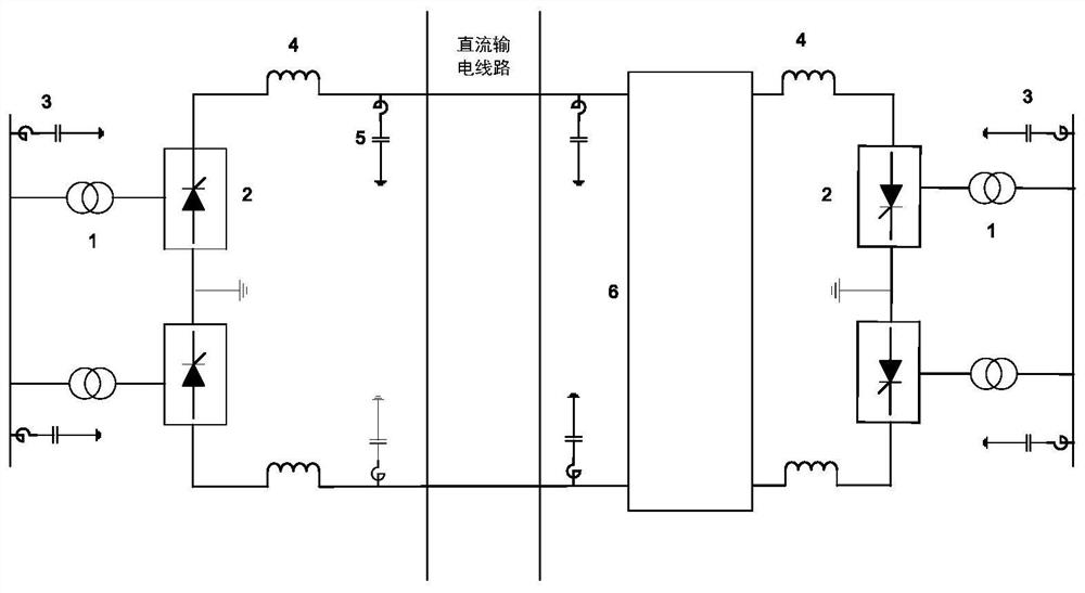
[0064] Specific embodiment one: apply the converter valve of the present invention to a converter system, such as figure 1 As shown, 1‐converter transformer, 2‐converter valve, 3‐AC filter, 4‐smoothing reactor, 5‐DC filter, 6‐DC side commutation bridge;

[0065] Both sides of the converter transformer 1 are respectively connected to the AC busbar and the converter valve 2, and the other end of the converter valve 2 is connected to the smoothing reactor 4 connected to one end of the DC line; the AC The filter 3 is connected between the AC bus and the ground; the DC filter 5 is connected in parallel between the DC line and the ground.

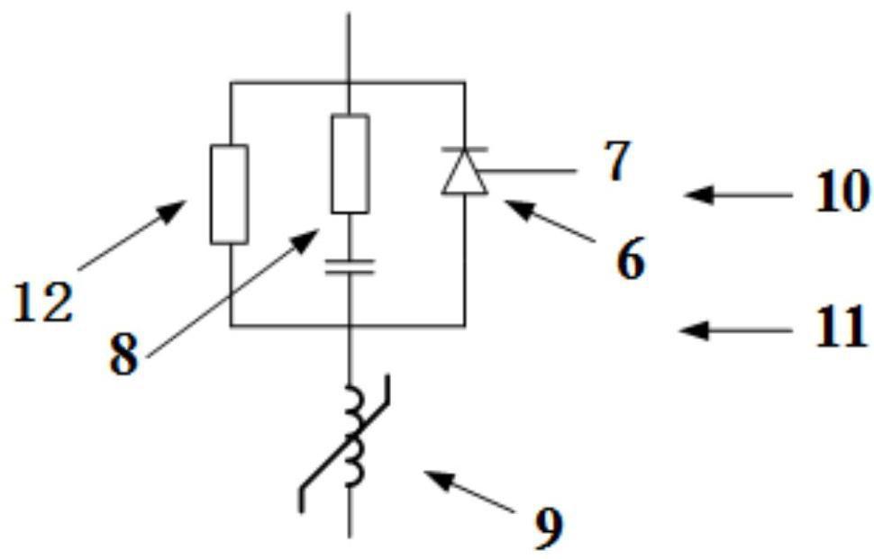
[0066] Such as figure 2 As shown, the converter valve 2 is mainly composed of 7, thyristor, 8, damping branch, 9, reactor, 10, trigger device and valve base electronic equipment, 11, cooling system, 12, voltage equalizing branch and other parts.

[0067] Thyristor, voltage equalizing branch, and damping branch are in parallel relationship. Aft...


PUM


Abstract

The present invention provides a method for optimizing a converter valve, which is characterized in that the converter valve includes: a reactor, a thyristor, a damping branch, a pressure equalizing branch, a trigger device, valve base electronic equipment, and a cooling system. The optimization method includes optimizing at least one of the thyristor, trigger device, valve base electronic equipment, reactor, damping branch, voltage equalizing branch and cooling system; the optimization of the thyristor is determined by determining the minimum turn-off angle of the thyristor Margins are implemented by way of suppression indicators. The invention optimizes the pressure equalizing branch parameters, reactor parameters and damping branch parameters of the converter valve, so that the dynamic shut-off characteristics of the thyristor are properly and beneficially affected, and the overall commutation characteristics, reliability and reliability of the converter valve equipment are improved. The degree of intelligence of the trigger monitoring device and the ability to withstand commutation failure and its severe consequences.

Description

technical field [0001] The invention relates to an optimization method, in particular to an optimization method for a converter valve. Background technique [0002] The converter valve is the core equipment of the DC transmission project. By sequentially connecting the three-phase AC voltage to the DC terminal to obtain the desired DC voltage and realize power control, its value accounts for about 22-25% of the total price of the complete set of equipment in the converter station. [0003] The commutation valve can be applied to a commutation system capable of resisting commutation failure, and is used to reduce or overcome commutation failure. Commutation Failure (CF) is a common fault form of UHVDC inverters. When the two valves commutate, the commutation process is not completed, or after the expected shut-off valve is turned off, the reverse voltage During this period, the blocking ability cannot be restored, and when the voltage applied to the valve is positive, it wil...

Claims


Application Information

Patent Timeline
Patent Type & Authority Patents(China)
IPC IPC(8): H02J3/36
CPCH02J3/36Y02E60/60
Inventor 许韦华汤广福贺之渊魏晓光杨杰庞辉
Owner GLOBAL ENERGY INTERCONNECTION RES INST CO LTD
Why Eureka
Try Eureka