
Indoor air conditioner with detachable bases

A detachable air-conditioning technology, applied in the field of air-conditioning, can solve the problems of air-conditioning water leakage, gaps, and increased air-conditioning mold development and manufacturing costs, and achieve the effect of reducing production costs, mold development and manufacturing costs

Pending Publication Date: 2017-08-08
AUX AIR CONDITIONING LTD BY SHARE LTD
View PDF7 Cites 2 Cited by
  • Summary
  • Abstract
  • Description
  • Claims
  • Application Information

AI Technical Summary

Problems solved by technology

But the existing base detachable air conditioner still has the following two deficiencies: the motor power used by the air conditioners of different powers is not the same, the motor power used by the air conditioner of high power is larger, and the motor power used by the air conditioner of low power is different. The power of the motor used in the air conditioner is small, and the size of the motors with different powers is not the same, which is mainly reflected in the length of the motor, that is, the length of the motor with higher power is longer, and the length of the motor with lower power is smaller Therefore, in order to meet the installation needs of motors with different powers, different models (with different powers) of the same style of air conditioner need to design a variety of lower bases with different lengths of motor slots, which undoubtedly greatly increases the mold development and manufacturing costs of the air conditioner. , thereby increasing the production cost of the air conditioner; 2. After the base adopts detachable upper base and lower base, the integrated drainage tank originally set on the base will also be separated up and down, so that the upper and lower parts of the drainage tank can be combined Finally, there will be gaps in the joint between the two, which will easily cause water leakage in the air conditioner.

Method used


Image

  • Indoor air conditioner with detachable bases
  • Indoor air conditioner with detachable bases
  • Indoor air conditioner with detachable bases

Examples


Embodiment Construction

[0038] The indoor air conditioner with detachable base of the present invention will be further described in detail below in conjunction with the accompanying drawings and specific embodiments.

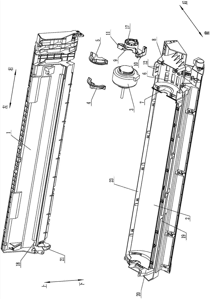
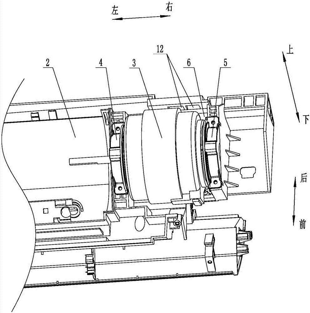
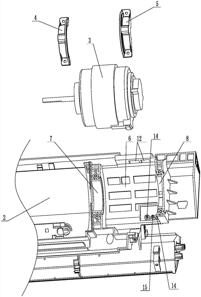
[0039] Such as Figure 1 to Figure 10 As shown, the indoor air conditioner with detachable base of the present invention includes a motor 3, a left fixed piece 4, a right fixed piece 5, and a detachable upper base 1 and a lower base 2. The lower base 2 is provided with a motor placement groove 6, and the motor is placed The left end of the slot 6 is provided with the left fixing part for fixing the motor 3 and is used to connect the left fixing seat 7 of the left fixing piece 4. The fixing seat 8, the indoor air conditioner with detachable base of the present invention also includes a second right fixing seat 9 for fixing the right end of the motor 3 and connecting the right fixing piece 5, the second right fixing seat 9 is detachably connected to the left Between the fixed seat 7 and ...


PUM


Abstract

The invention relates to an indoor air conditioner with detachable bases. The air conditioner comprises a motor (3), a left fixing piece (4), a right fixing piece (5), a second right fixing base (9), the detachable upper base (1) and the detachable lower base (2); a motor containing groove (6) is formed in the lower base (2), the second right fixing base (9) is connected into the motor containing groove (6), an upper water groove (18) is formed in the lower portion of the upper base (1), a front water groove (19) is formed in the front portion of the lower base (2), a side water groove (20) communicated with the front water groove (19) is formed in the left side of the lower base (2), and a water guide nozzle (21) for guiding condensate water in the upper water groove (18) to the side water groove (20) is formed in the left side of the upper base (1). The indoor air conditioner has the beneficial effects that the mold development and manufacturing cost of the air conditioner can be greatly reduced, the air conditioner production cost is reduced, and water leakage of the air conditioner is prevented.

Description

technical field [0001] The invention relates to an air conditioner, in particular to an indoor air conditioner with a detachable base. Background technique [0002] At present, the base of a traditional air conditioner is usually integral. Since the base is connected with heat exchangers, copper pipes and other components, the base cannot be disassembled separately. When components with a high failure rate such as electronic controls need maintenance, the staff can only disassemble the air conditioner, which is not only troublesome to operate, but also greatly increases the difficulty of maintenance for the staff. In order to solve the above problems, the base of some existing air conditioners adopts a split structure, that is, the base is divided into an upper base and a lower base. On the upper base, install components with high failure rates such as indoor motors, fan blades, and electric controls on the lower base, so that when components with high failure rates such as...

Claims


Application Information

Patent Timeline
IPC IPC(8): F24F1/00F24F13/22F24F13/32
CPCF24F1/0007F24F13/22F24F13/32
Inventor 张坤鹏古汤汤秦宪张华中倪晓龙邓楠蔡广隆豪
Owner AUX AIR CONDITIONING LTD BY SHARE LTD
Learn More