Ground state detection unit, grounding device and ground state detection method
A technology of grounding state and detection unit, which is applied in the direction of measuring device, measuring electricity, measuring electric variables, etc., to achieve the effect of direct interlocking judgment basis and reliable detection
- Summary
- Abstract
- Description
- Claims
- Application Information
AI Technical Summary
Problems solved by technology
Method used
Image
Examples
Embodiment 1
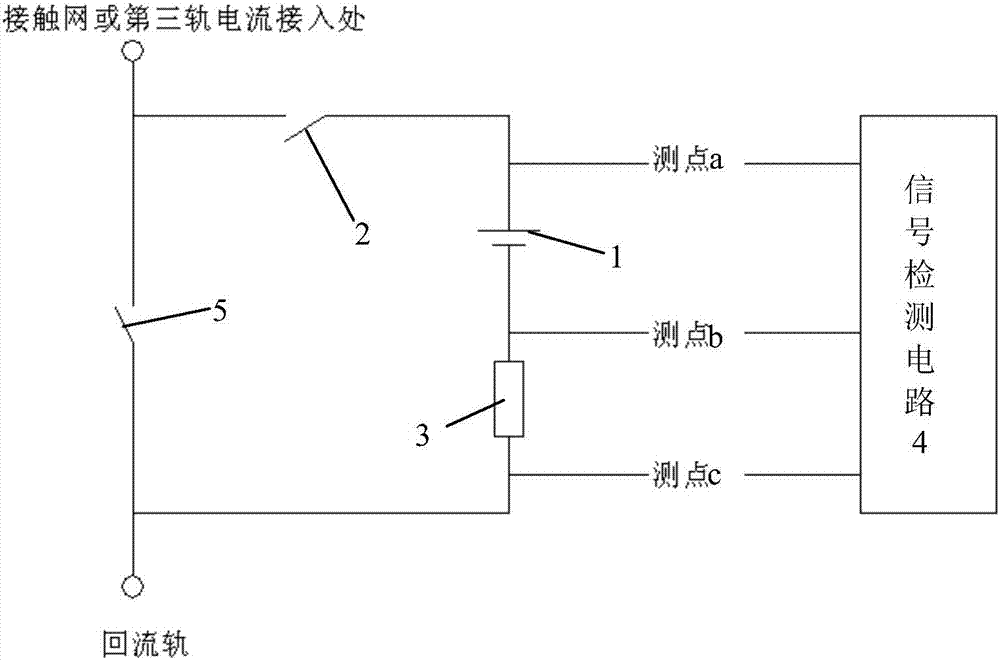
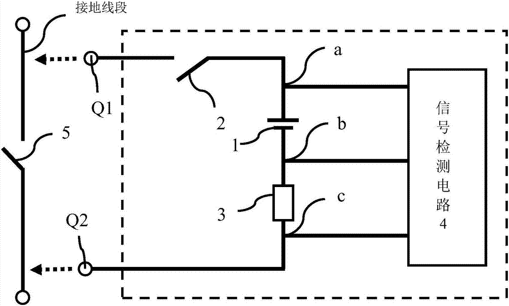
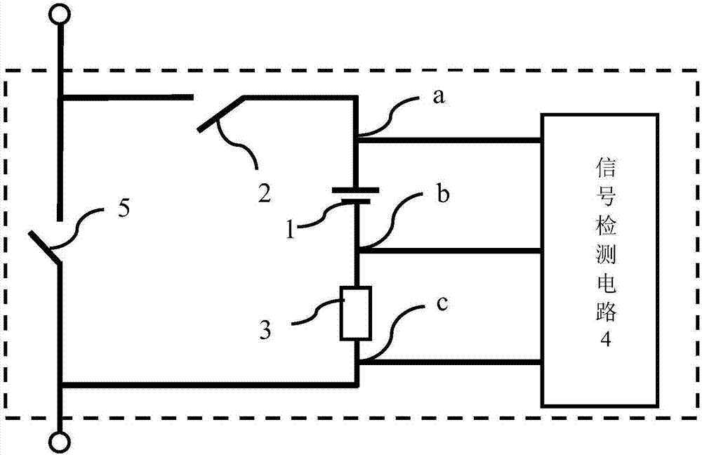
[0053] Such as figure 1 As shown, the grounding state detection unit for the subway track catenary in this embodiment includes a signal current source 1, a signal switch 2, a standard resistor 3 and a signal detection circuit 4, a signal switch 2, a signal current source 1, a standard resistor 3 in series in sequence. The grounding state detection unit is connected to both sides of the grounding switch 5 on the return rail of the catenary, and the signal switching switch 2, the signal current source 1, the standard resistor 3, and the grounding switch 5 form a measurement circuit. The first detection point a is set between the signal changeover switch 2 (grounding switch) and the signal current source 1, the second detection point b is set between the signal current source 1 and the standard resistor 3, and the second detection point b is set between the standard resistor 3 and the grounding switch 5 The third detection point c is set between them, the number of detection poi...
Embodiment 2
[0063] In the foregoing embodiments, the signal detection circuit is a voltage detection circuit. After measuring the voltage at the detection point through the voltage detection circuit, the grounding resistance of the grounding switch is then calculated to determine the grounding state. The difference between this embodiment and Embodiment 1 is that this implementation The signal detection circuit 4 of example is a control module with voltage detection function, such as Figure 4 As shown, the control module is provided with a feedback unit. The feedback unit in this embodiment is a status indicator light. The control module can be a commercially available integrated module with voltage detection function and programming calculation function. The control module collects the voltage data of each detection point Finally, the result is automatically calculated and judged, and the feedback information is fed back through the feedback unit. For example, the green light indicates g...
Embodiment 3
[0066] The difference between this embodiment and embodiment 2 is: as Figure 5 As shown, this embodiment is also provided with an electric control actuator 6 electrically connected to the control module, and the electric control actuator 6 is used to control the opening / closing of the grounding switch 5 and / or the signal switching switch 2 . The control module sends instructions to the electric control actuator 6 to control it to open and close the grounding switch 5 and / or the signal switching switch 2, eliminating the need for manual operation, and realizing remote operation and automatic operation. Further, in this embodiment, a locking device 7 is provided at the grounding switch 5 , the locking device 7 is electrically connected to the control module, and the locking device 7 can lock the grounding switch 5 after the grounding switch 5 is closed. When the control module detects that the grounding switch 5 has been reliably grounded, the control module controls the lockin...
PUM
 Abstract
Description
Claims
Application Information
 - R&D
- Intellectual Property
- Life Sciences
- Materials
- Tech Scout
- Unparalleled Data Quality
- Higher Quality Content
- 60% Fewer Hallucinations
Browse by: Latest US Patents, China's latest patents, Technical Efficacy Thesaurus, Application Domain, Technology Topic, Popular Technical Reports.
© 2025 PatSnap. All rights reserved.Legal|Privacy policy|Modern Slavery Act Transparency Statement|Sitemap|About US| Contact US: help@patsnap.com


