Geological disaster automatic monitoring device and method of surface stay cable force measurement type

A technology of geological disasters and monitoring devices, which is applied in the direction of measuring devices, tension measurement, instruments, etc., to achieve the effects of early detection, low cost and high coverage density

Pending Publication Date: 2017-08-04
北京中船信息科技有限公司
View PDF13 Cites 1 Cited by
  • Summary
  • Abstract
  • Description
  • Claims
  • Application Information

AI Technical Summary

Problems solved by technology

[0007] The purpose of the present invention is to provide a surface cable force measurement type geological disaster automatic monitoring device and method, thereby solving the aforementioned problems existing in the prior art

Method used


Image

  • Geological disaster automatic monitoring device and method of surface stay cable force measurement type
  • Geological disaster automatic monitoring device and method of surface stay cable force measurement type
  • Geological disaster automatic monitoring device and method of surface stay cable force measurement type

Examples


Embodiment 1

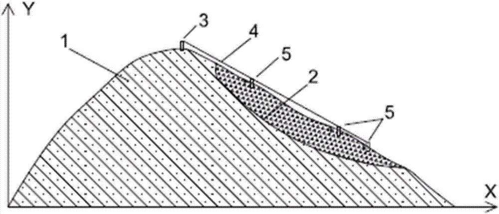
[0029] Reference figure 1 , The surface cable force measurement type geohazard automatic monitoring device of this embodiment includes: a remote monitoring terminal and a tension test unit;

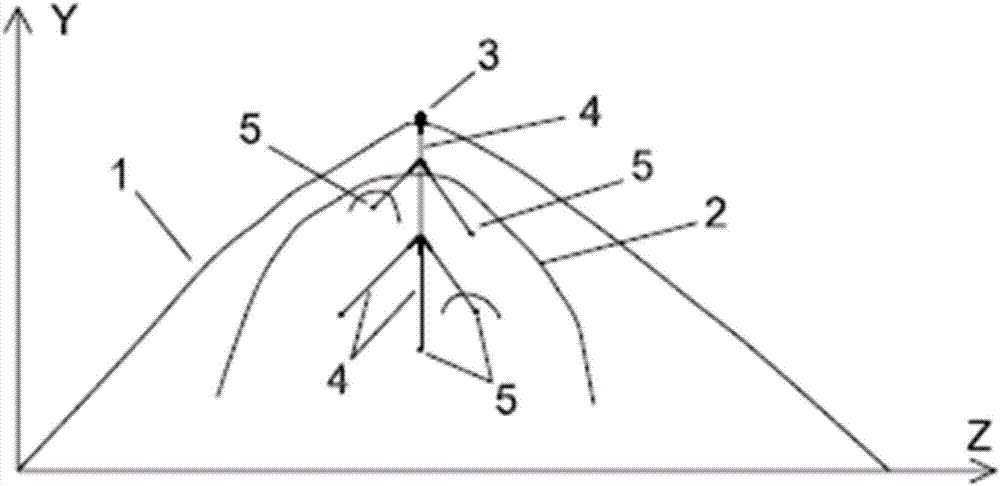
[0030] The tension test unit includes a fixed pile 3 and a tension net, the tension net includes a main bearing cable, 5 branch cables and 5 pre-monitoring point anchor piles 5;

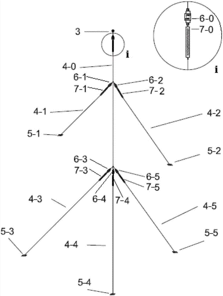
[0031] The fixed pile 3 is arranged on the top of the mountain to be monitored for the landslide, one end of the main load-bearing cable 4-0 is connected to the fixed pile 3 through a main load cell, and the main load-bearing cable 4- The other end of 0 is connected with three corresponding pre-monitoring point anchor piles (5-3, 5-4, 5-5) through three branch cables (4-3, 4-4, and 4-5). Two branch load cells 6-1 and 6-2 are also arranged on the cable body of the load-bearing stay cable 4-0; the main load cell and all branch load cells are wirelessly connected to the remote monitoring terminal.

[0032] A more detaile...

Embodiment 2

[0039] This embodiment is based on the automatic monitoring method of the surface cable force-measuring automatic monitoring device for geological hazards described in embodiment 1, and the method includes:

[0040] S1: Obtain the landslide A to be monitored, and set multiple anchor piles at pre-monitoring points on the landslide A to be monitored;

[0041] A fixed pile is set on the top of the mountain where the landslide A to be monitored is located, and the fixed pile is connected to the main load-bearing cable through the main load cell, and each pre-monitoring point anchor pile passes the branch load cell to its one-to-one corresponding branch cable Connected to the main load-bearing cable; between the main load-bearing cable and the main load cell, a pre-tightening force is set between the branch cable and the anchor pile at the pre-monitoring point spring;

[0042] After tensioning all the pretension springs, complete the installation of the tension net A on the landslide A t...


PUM


Abstract

The invention discloses a geological disaster automatic monitoring device and method of a surface stay cable force measurement type, and relates to the field of geological disaster monitoring. The device comprises a remote monitoring end and at least one tension testing units. Each tension testing unit comprises one fixed pile and at least one tension net, wherein each tension net comprises a main force-bearing stay cable, n branch stay cables and n preset monitoring point anchor piles. The method comprises the steps: setting the device on a to-be-monitored slope A, obtaining and recording the basic monitoring value of each force measurement sensor on any one tension net A on the to-be-monitored slope A, and judging whether landslide happens to the to-be-monitored slope A or not through the changes of all force measurement sensors on the device. According to the invention, the device can achieve the direct monitoring of the tendency of the potential energy of a landslide mass through the stay cable force measurement type, is simple and convenient in implementation, is low in cost, is high in coverage density of regional monitoring points, and can find the symptom of landslide early.

Description

Technical field [0001] The invention relates to the field of geological disaster monitoring, in particular to a surface cable force measurement type geological disaster automatic monitoring device and method. Background technique [0002] Subsidence monitoring is an important monitoring feature of landslides. The existing landslide monitoring methods mainly include surface displacement monitoring (that is, high-precision satellite navigation and positioning), crack gauges, deep displacement inclinometers, earth pressure boxes and other monitoring methods. These methods currently There are problems such as limited application range, high cost, insufficient monitoring point density, etc., specifically: [0003] 1. High-precision satellite navigation and positioning measurement is to receive Beidou and GPS satellite signals for differential RTK calculation, and use the principle of radio ranging to calculate the positioning accuracy of several millimeters with a distance of 20,000 to ...

Claims


Application Information

Patent Timeline
IPC IPC(8): G01B21/02G01L5/04
CPCG01B21/02G01L5/04
Inventor 周敏高斌严璐
Owner 北京中船信息科技有限公司
Why Eureka
Try Eureka