Cylindrical multi-roller bearing seat

A technology of roller bearings and cylinders, which is applied in the direction of bearing components, shafts and bearings, rigid supports of bearing components, etc., can solve the problems of reducing frictional resistance, small axial bearing capacity, low speed axis, etc., and achieve axial and The effect of improving radial bearing capacity, overcoming low axial bearing capacity, and overcoming fatal defects

Inactive Publication Date: 2017-08-04
响水县翔宇传动件有限公司
View PDF8 Cites 0 Cited by
  • Summary
  • Abstract
  • Description
  • Claims
  • Application Information

AI Technical Summary

Problems solved by technology

[0002] Although the existing technology can greatly reduce the frictional resistance, it can generally only be used for equipment or shimmy equipment running in opposite directions at the same time, or for large rollers with low speed and unstable shaft center. The experimental conclusion of compensating for eccentricity and reducing starting resistance, because multi-ring bearings have serious defects when operating at slightly higher speeds or under heavy loads, traditional multi-ring bearings have diameter differences, and each The frictional resistance of the rolling elements of the layers is very different, and it is difficult to achieve synchronous rotation or cannot rotate at the same time, which is very unfavorable to reduce frictional resistance. The outer ring of the existing self-aligning bearing basically adopts the ring with the largest spherical diameter as the inner track. , the contact angle between the inner track of the spherical surface with the largest diameter and the rolling elements is the smallest, forming a congenital defect that the axial bearing capacity is too small, and the axial load-bearing rolling elements of the existing top bearings and self-aligning bearings are all single-row structure, the axial bearing capacity is too small to meet the requirements of actual use

Method used


Image

  • Cylindrical multi-roller bearing seat
  • Cylindrical multi-roller bearing seat

Examples


Embodiment Construction

[0013] The technical solutions in the embodiments of the present invention will be clearly and completely described below in conjunction with the accompanying drawings in the embodiments of the present invention. Obviously, the described embodiments are only a part of the embodiments of the present invention, rather than all the embodiments. Based on the embodiments of the present invention, all other embodiments obtained by those of ordinary skill in the art without creative work shall fall within the protection scope of the present invention.

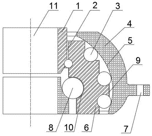
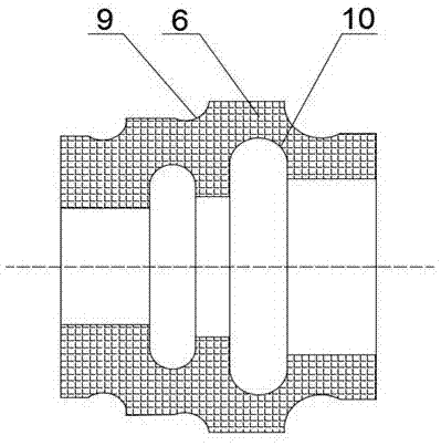
[0014] See Figure 1-2 , The present invention provides a technical solution: a cylindrical multi-roller bearing seat, including a bladder-type outer ring 4, a variable-diameter intermediate layer ring 6, an inner ring 1 and an outer rolling element 3, which are successively from the outside to the inside The bladder-type outer ring 4, outer rolling element 3, variable-diameter intermediate layer ring 6 and inner ferrule 1, the bladder-t...


PUM


Abstract

The invention discloses a cylindrical multi-roller bearing seat. The cylindrical multi-roller bearing seat sequentially comprises a ball bladder type outer ring, an outer rolling body, a diameter-variable interlayer ring, and an inner ring from outside to inside, wherein shaft mounting holes are formed in both the upper and the lower ends of the shaft axis of the ball bladder type outer ring, screw mounting holes are formed in both the left and right ends of the ball bladder type outer ring, and a ball bladder type outer ring inner ball bladder track is formed on the inner side of the ball bladder type outer ring; the outer rolling body comprises at least two rows of cylinders for bearing axial force; the ball bladder type outer ring inner ball bladder track is a circular ball bladder inner track; and an outer rolling wheel is connected with the diameter-variable interlayer ring, an outer track groove is formed in the outer side of the diameter-variable interlayer ring, and an inner groove track is formed in the inner side of the diameter-variable interlayer ring. The cylindrical multi-roller bearing seat can substantially improve the bearing capacity of the interlayer ring, effectively control the stability of the bearing interlayer ring in the process of high-speed rotating, and further greatly improve the bearing capacity of a multi-roller layer bearing.

Description

Technical field [0001] The invention relates to the technical field of bearings, in particular to a cylindrical multi-roller bearing seat. Background technique [0002] Although the existing technology can greatly reduce the friction resistance, it can only be used for equipment or oscillating equipment running in opposite directions at the same time, or for large rollers with low speed and unstable axis. Compensate for the experimental conclusions of eccentricity and reduce starting resistance, because the multi-ring bearing will have serious defects when running at a slightly higher speed or under heavy load. The traditional multi-ring bearing has the problem of diameter difference. The friction resistance of the rolling elements of the layer is very different, it is difficult to realize synchronous rotation or cannot rotate at all, which is very unfavorable to reduce the friction resistance. The outer ring of the existing self-aligning bearing basically uses the ring with the ...

Claims


Application Information

Patent Timeline
Patent Type & Authority Applications(China)
IPC IPC(8): F16C35/06
CPCF16C35/061
Inventor 董郁春
Owner 响水县翔宇传动件有限公司
Why Eureka
Try Eureka