Wind power generation equipment
A technology for wind power generation equipment and linear motors, which is applied to wind power generation, wind turbines, and wind turbines in the same direction as the wind, can solve problems such as easy failure and inconvenience, achieve simple structure, and save maintenance and repair time. effect with human
- Summary
- Abstract
- Description
- Claims
- Application Information
AI Technical Summary
Problems solved by technology
Method used
Image
Examples
Embodiment 1
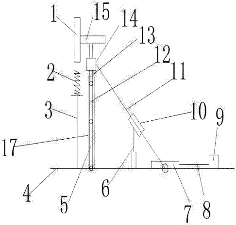
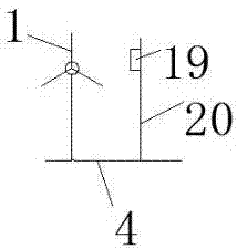
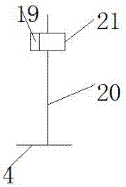
[0015] Embodiment 1, a kind of wind power generation equipment, comprises: blade 1, ground 4, first upright rod 5, hydraulic lifting device 6, first slider 7, piston rod 8, pneumatic cylinder 9, second slider 10, inclined Rod 11, second vertical rod 12, third vertical rod 13, clip 14, machine head 15, semicircular splint 17, bolt 18, thermal imager 19, vertical linear motor guide rail 20, linear motor 21; where: the first vertical rod 5 is hinged with the ground 4; the first vertical rod 5, the second vertical rod 12, and the third vertical rod 13 are hinged and connected successively; the top of the third vertical rod 13 is fixedly installed with the machine head 15; There are blades 1; the third vertical rod 13 is fixedly provided with a clip 14; one side of the clip 14 is hinged with one end of the oblique rod 11; the other end of the oblique rod 11 is hinged with the first slider 7; the first slider 7 is connected with the The ground 4 is slidingly connected; the first sli...
Embodiment 2
[0018] Embodiment 2. A wind power generation device, wherein: the lower part of the blade 1 is provided with an enameled coil 2; the enameled coil 2 is connected to the ground 4 through a support rod 3, and a layer of permanent magnetic material is provided on the outer surface of the blade 1. All the other are with embodiment 1.
Embodiment 3
[0019] Embodiment 3. A wind power generation device, wherein: the outer wall of the machine head 15 is provided with a thermoelectric power generation sheet. All the other are with embodiment 1.
[0020] Working principle: when the nose 15 is to be lowered,
[0021] The two sides of each semicircle splint 17 can respectively be provided with a row of through holes, or a through hole; two semicircle splints 17 can be fixedly connected by two rows of bolts 18 through the through holes and nuts; A semicircle splint 17, the first slide block 7 moves backward, and the hydraulic lifting device 6 begins to descend; Described hydraulic lifting device 6 can be a hydraulic cylinder; By the piston rod on the hydraulic cylinder being hinged with the second slide block 10;
[0022] The second vertical rod 12, the third vertical rod 13, and the first vertical rod 5 begin to bend until the machine head 15 falls to a suitable position; thereby making it convenient for staff to maintain; the ...
PUM
 Abstract
Description
Claims
Application Information
 - R&D
- Intellectual Property
- Life Sciences
- Materials
- Tech Scout
- Unparalleled Data Quality
- Higher Quality Content
- 60% Fewer Hallucinations
Browse by: Latest US Patents, China's latest patents, Technical Efficacy Thesaurus, Application Domain, Technology Topic, Popular Technical Reports.
© 2025 PatSnap. All rights reserved.Legal|Privacy policy|Modern Slavery Act Transparency Statement|Sitemap|About US| Contact US: help@patsnap.com


