
Glass hot bending former with improved pushing mechanisms

A pusher mechanism and molding machine technology, which is applied in glass molding, glass reshaping, glass manufacturing equipment, etc., can solve problems such as low service life, generation of powder chips, aging drive cylinders, etc., to improve the life of the whole machine , the effect of a reasonable structure

Inactive Publication Date: 2017-08-04
汕头市龙湖区可期机械设备科技有限公司
View PDF4 Cites 1 Cited by
  • Summary
  • Abstract
  • Description
  • Claims
  • Application Information

AI Technical Summary

Problems solved by technology

[0004] With the continuous popularization of curved screens and 2.5D curved display screens, in order to protect the display screen made of glass, most people will choose to use tempered glass to cover and protect the outside of the screen, and the current processing equipment for glass is to heat the glass in a sealed cavity. And with the mold for thermal processing, the feeding mechanism needs to perform the pushing action of the rotary path, so two sets of horizontal and vertical drive cylinders are required. In order to achieve air tightness, the two sets of drive cylinders of the existing hot bending equipment have one set It will be set in the sealed chamber and move with the drive of another set, and the sealed chamber is a high-temperature environment, and the driving cylinder in the sealed chamber is prone to aging and failure, resulting in a relatively low service life
However, the traditional cam drive will generate dust due to friction, which is not suitable for use in glass hot bending forming machines.

Method used


Image

  • Glass hot bending former with improved pushing mechanisms
  • Glass hot bending former with improved pushing mechanisms

Examples


Embodiment Construction

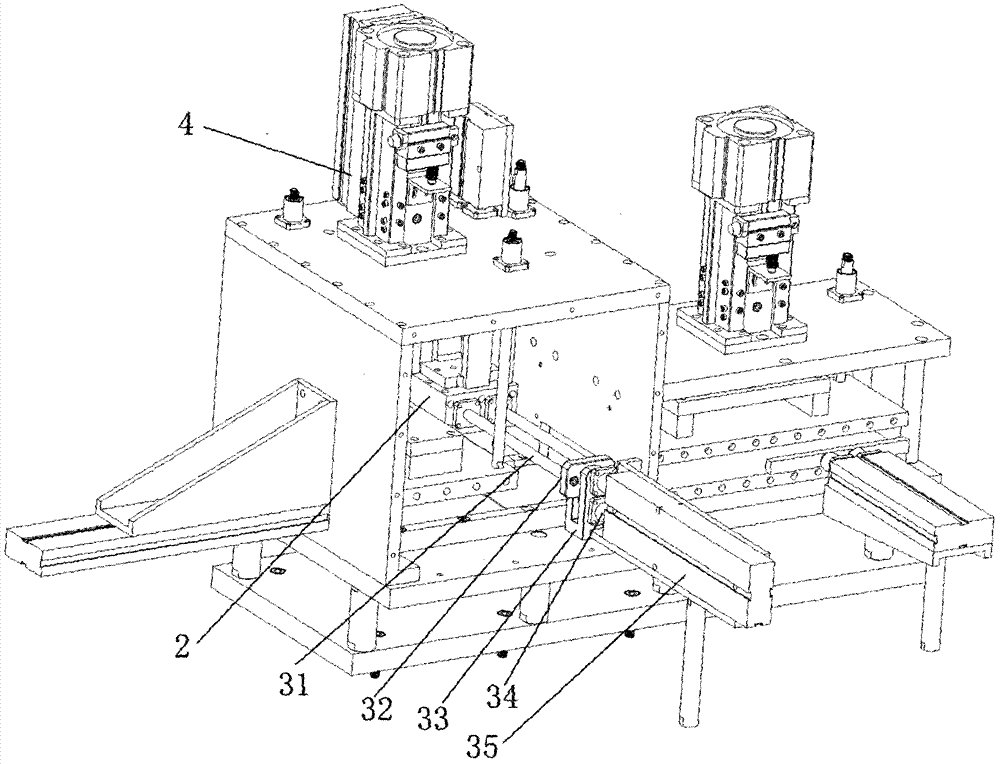
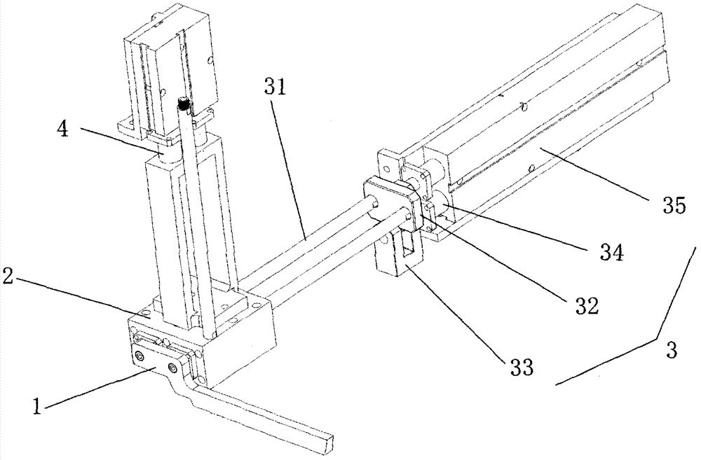
[0016] Such as Figure 1 to Figure 2 As shown, a glass hot bending forming machine with an improved pushing mechanism is characterized in that the glass hot bending machine includes a body and a material suction station, a material pushing station, and a plurality of hot bending stations connected in sequence on the body , The discharge station, the body is provided with a heat-insulated air-tight cavity, and the suction station, pusher station, hot-bending station, and discharge station are all set in the heat-insulated air-tight cavity , the push station includes a push rod 1, a push block 2, a horizontal push mechanism 3 and a vertical push mechanism 4 connected to the push block, and the horizontal push structure 3 includes a push rod 31, a guide slider 32, a guide Groove block 33, driving rod 34 and horizontal driving cylinder 35, the horizontal driving cylinder is arranged outside the heat-insulating airtight chamber, the horizontal driving rod is connected to the horizo...


PUM


Abstract

A glass hot bending former with improved pushing mechanisms comprises a former body, and a horizontal pushing mechanism and a vertical pushing mechanism that are located in the former body, wherein the horizontal pushing mechanism comprises pushing rods, a guide slider, a guide groove block, a driving rod and a horizontal driving air cylinder; the horizontal driving air cylinder is arranged outside a heat insulation airtight cavity; the horizontal driving rod is connected with the horizontal driving air cylinder; the horizontal driving rod penetrates through a side wall of the heat insulation airtight cavity and is connected with the guide groove block; the guide groove block is provided with a guide groove; the guide slider slides in the guide groove; the depth of the guide groove is greater than the movement depth of the horizontal pushing mechanism for ensuring that the guide slider keeps connection with the guide groove block in a movement process; and the pushing rods are connected with a pushing block. One driving rod of two driving air cylinders of the pushing structures adopts a structure that a slide groove and a slider are matched with each other and keep connection; the two driving air cylinders are arranged outside the heat insulation airtight cavity, so that the influence on service lives of the driving air cylinders caused by overheating is avoided; and the hot bending former has the advantages that the hot bending former is reasonable in structure, and the life of the whole hot bending former can be prolonged significantly.

Description

[0001] Technical field: [0002] The invention belongs to the processing equipment of the outer protective glass of the curved display screen in the field of hot bending of glass, and in particular relates to a glass hot bending forming machine with an improved pushing mechanism. [0003] Background technique: [0004] With the continuous popularization of curved screens and 2.5D curved display screens, in order to protect the display screen made of glass, most people will choose to use tempered glass to cover and protect the outside of the screen, and the current processing equipment for glass is to heat the glass in a sealed cavity. And with the mold for thermal processing, the feeding mechanism needs to perform the pushing action of the rotary path, so two sets of horizontal and vertical drive cylinders are required. In order to achieve air tightness, the two sets of drive cylinders of the existing hot bending equipment have one set It will be set in the sealed chamber and m...

Claims


Application Information

Patent Timeline
IPC IPC(8): C03B23/023
CPCC03B23/023C03B2225/00
Inventor 林仲
Owner 汕头市龙湖区可期机械设备科技有限公司
Learn More