An integrated clutch-transmission system with a clutch cage carrying gearwheels

A technology of transmission gears and power transmission systems, which is applied in the directions of transmission parts, belts/chains/gears, control devices, etc., to achieve the effect of simplifying the structure, compacting the structure and reducing the axial structure space

Inactive Publication Date: 2017-08-04
SCHAEFFLER TECH AG & CO KG
View PDF7 Cites 1 Cited by
  • Summary
  • Abstract
  • Description
  • Claims
  • Application Information

AI Technical Summary

Problems solved by technology

[0003] However, it has been found to be disadvantageous in the known solutions that the clutch transmission system is usually designed relatively large, especially in the axial direction.

Method used


Image

  • An integrated clutch-transmission system with a clutch cage carrying gearwheels
  • An integrated clutch-transmission system with a clutch cage carrying gearwheels

Examples


Embodiment Construction

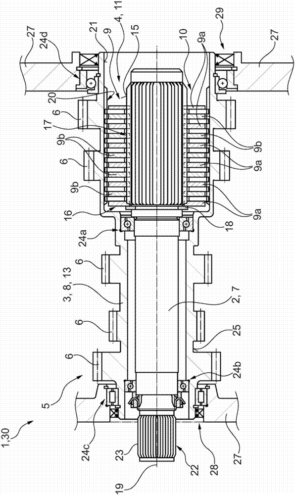
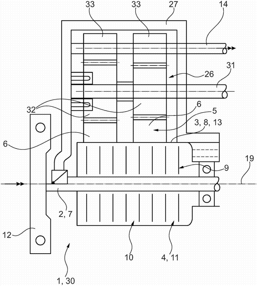
[0029] combine figure 2 , first of all, the installed state of the clutch transmission system 1 according to the invention according to a preferred exemplary embodiment can be seen in principle. The clutch transmission system 1 is intended to be arranged in the drive train of the motor vehicle, viewed in the line of force / torque, between the internal combustion engine of the motor vehicle and the driven wheels / tyres of the motor vehicle. The clutch transmission system 1 forms a transmission 30 in this embodiment. The transmission 30 is designed here as a manual transmission, but is not restricted to this embodiment. According to a further embodiment, the transmission 30 is also designed as an automatic transmission, for example an automated / automatic dual clutch transmission.

[0030] During operation, the first rotating part 2 of the clutch transmission system 1 is connected in a rotationally fixed manner to the output shaft of the internal combustion engine, which is desi...


PUM


Abstract

The invention relates to a clutch-transmission system (1) for a drive train of a motor vehicle, comprising a clutch device (4) with a first rotary part (2) and a second rotary part (3) which is non-rotatably connected to the first rotary part (2) in at least one engaged position and at least partially surrounds the first rotary part (2) radially from outside. The second rotary part (3) is designed as a component of a transmission device (5) and bears at least one transmission gearwheel (6) of a gear ratio stage. The invention relates to a drive train for a motor vehicle with such a clutch-transmission system (1).

Description

technical field [0001] The present invention relates to a clutch transmission system (also referred to as a clutch transmission unit) for a power train of a motor vehicle, that is, a clutch integrated in a transmission, such as a passenger car, a bus, a truck or Agricultural vehicles, the clutch transmission system having a clutch device with a first rotary part and a second rotary part, the second rotary part is in at least one coupling point (of the clutch device) with the first rotary part The connection is fixed against rotation, wherein the second rotary part surrounds the first rotary part at least partially radially from the outside (relative to the axis of rotation of the clutch transmission / rotary part). Furthermore, the invention directly relates to a drive train for a motor vehicle having such a clutch transmission system. Background technique [0002] Clutch transmission systems are known from the prior art, which are designed, for example, as transmissions and ...

Claims


Application Information

Patent Timeline
IPC IPC(8): B60K17/02B60K17/08
CPCB60K17/02B60K17/08F16H57/0025
Inventor 延斯·古拉施卡尔-路德维希·基米希
Owner SCHAEFFLER TECH AG & CO KG
Why Eureka
Try Eureka