
Printed circuit board (PCB) body fixing die moving device for PCB cutting machine

A technology for moving PCB boards and molds, applied in metal processing, etc., can solve the problems of troublesome installation and disassembly, low degree of automation, easy damage to the board, etc., and achieve the effect of firm fixation and convenient installation and disassembly

Active Publication Date: 2017-08-04
天津光电集团有限公司
View PDF6 Cites 5 Cited by
  • Summary
  • Abstract
  • Description
  • Claims
  • Application Information

AI Technical Summary

Benefits of technology

This new technology allows for easy installation or removal without having any extra steps like rewiring. It also makes sure that there's no damage caused by moving parts during operation.

Problems solved by technology

This patented technical problem addressed in this patents relates to improving the performance and productivity of electronic devices' printed circuit boards (PCs) due to their being too rigid or damaged easily during installation. Mechanic Sub-Board technology has been developed but these methods require expensive tools for fixing them with screws that can make assembly time longer than desired. Additionally, there may also be issues related to moving mechanisms such as manually adjusting position on large panels without causing any harm themselves.

Method used


Image

  • Printed circuit board (PCB) body fixing die moving device for PCB cutting machine
  • Printed circuit board (PCB) body fixing die moving device for PCB cutting machine

Examples


Embodiment Construction

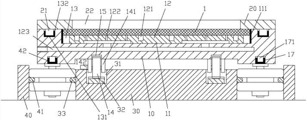
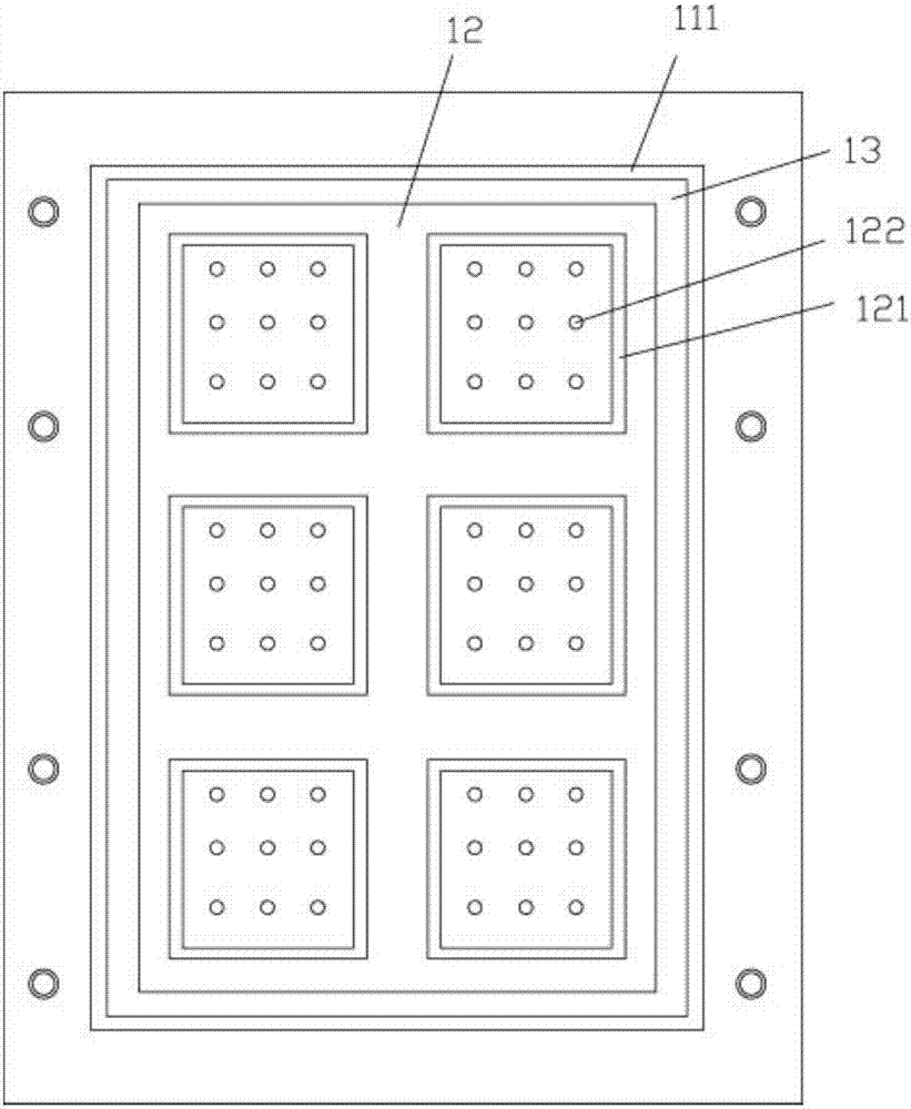
[0027] Examples, see e.g. Figure 1 to Figure 2 As shown, a PCB board body fixed mold moving device for a PCB splitter includes a lower mold 10 and a lower center rail bar 30, the lower center rail bar 30 is located below the lower mold 10, and the middle part of the top surface of the lower mold 10 There is a placement groove 11, the bottom surface of the placement groove 11 has a mounting raised plate 12, there is a hollow groove 13 between the mounting raised plate 12 and the inner side wall of the placing groove 11, and the middle part of the mounting raised plate 12 has a plurality of square Groove 121, the mounting raised plate 12 in the middle of the square groove 121 has a plurality of ventilation holes 122, the side wall of the lower mold 10 has a plurality of communication holes 123, and the ventilation holes 122 communicate with the communication holes 123;

[0028] The top surface edge of the lower mold 10 has a plurality of positioning concave holes 131, the upper...


PUM


Abstract

The present invention discloses a printed circuit board (PCB) body fixing die moving device for a PCB cutting machine. The moving device comprises a lower die and a lower central rail strip, the lower central rail strip is disposed below the lower die, a placing groove is disposed in the central part of the top face of the lower die, an installation convex plate is arranged on the bottom face of the placing groove, a hollow groove is disposed between the installation convex plate and the inner side wall of the placing groove, the middle part of the installation convex plate is provided with a plurality of square grooves, the installation convex plate in the middle part of each square groove is provided with a plurality of vent holes, the side wall of the lower die is provided with a plurality of communication holes, and the vent holes are communicated with the communication holes. The side part of the top face of the lower die is provided with a plurality of positioning dent holes, an upper press plate is pressed against the top face of the lower die, the side part of the bottom face of the upper press plate is provided with raised columns, the raised columns are inserted into the corresponding positioning dent holes, and the middle part of the upper press plate is provided with a main through slot. The PCB body fixing die moving device can automatically fix PCB bodies and automatically move, realizing automatic transportation. Moreover, the fixing is firm, and the installation and disassembly are convenient.

Description


Claims


Application Information

Patent Timeline
Owner 天津光电集团有限公司
Learn More