
Cuboid-shaped 3D printing equipment and 3D printer

A 3D printing, cuboid-shaped technology, applied in the direction of process efficiency improvement, additive manufacturing, additive processing, etc., can solve the problem of low levelness of the metal powder layer, achieve the effect of improving the density and surface finish, and improving the levelness

Active Publication Date: 2017-08-04
窦鹤鸿
View PDF3 Cites 1 Cited by
  • Summary
  • Abstract
  • Description
  • Claims
  • Application Information

AI Technical Summary

Problems solved by technology

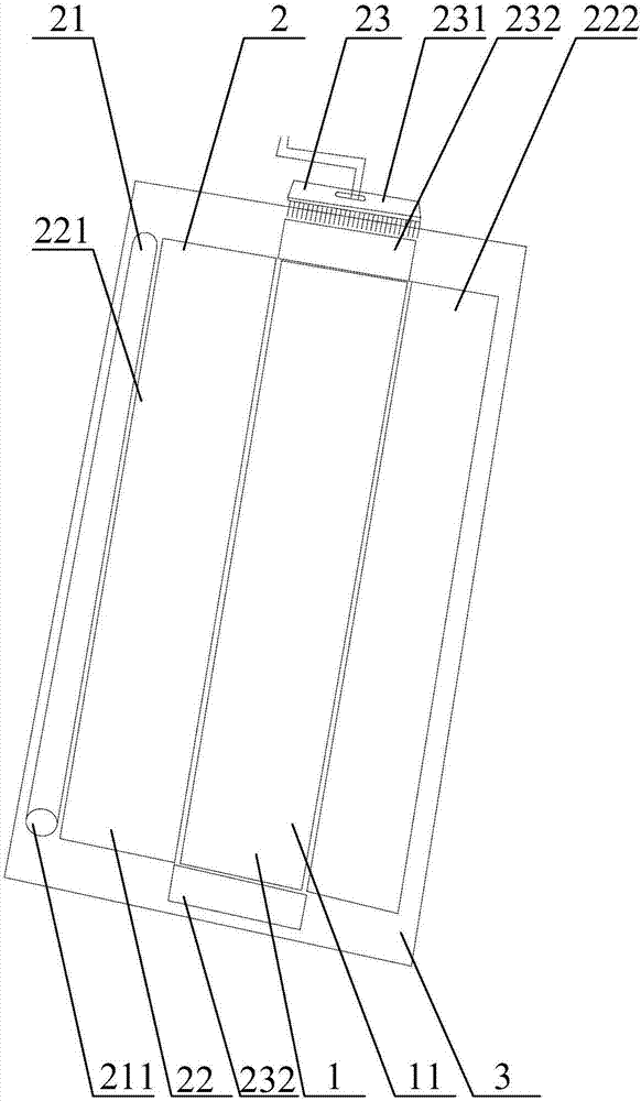
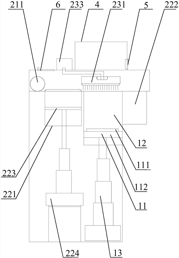
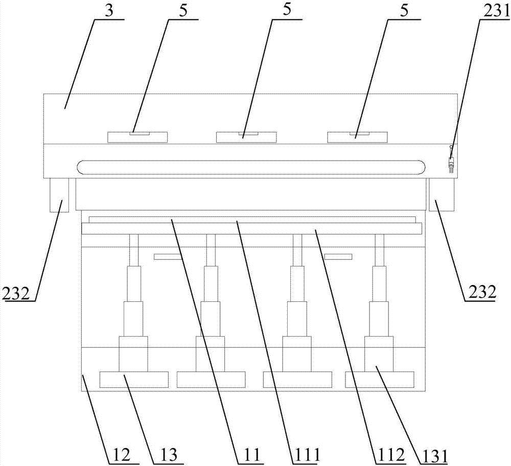
[0006] The purpose of the present invention is to provide a cuboid 3D printing equipment and a 3D printer to solve the technical problem of low flatness of the metal powder layer on the workbench existing in the prior art

Method used


Image

  • Cuboid-shaped 3D printing equipment and 3D printer
  • Cuboid-shaped 3D printing equipment and 3D printer
  • Cuboid-shaped 3D printing equipment and 3D printer

Examples


Embodiment Construction

[0029] The technical solutions of the present invention will be clearly and completely described below in conjunction with the accompanying drawings. Apparently, the described embodiments are some of the embodiments of the present invention, but not all of them. Based on the embodiments of the present invention, all other embodiments obtained by persons of ordinary skill in the art without making creative efforts belong to the protection scope of the present invention.

[0030] In the description of the present invention, it should be noted that the terms "center", "upper", "lower", "left", "right", "vertical", "horizontal", "inner", "outer" etc. The indicated orientation or positional relationship is based on the orientation or positional relationship shown in the drawings, and is only for the convenience of describing the present invention and simplifying the description, rather than indicating or implying that the referred device or element must have a specific orientation, ...


PUM


Abstract

The invention relates to the technical field of selective laser melting metal 3D printing, in particular to cuboid-shaped 3D printing equipment and a 3D printer. The cuboid-shaped 3D printing equipment comprises construction-forming device and a powder supplying system. A powder laying device is used for laying metal powder in a powder feeding device on an operation platform in a rolling-type powder laying mode. A powder flattening piece driving mechanism is connected with a powder flattening piece and used for driving the powder flattening piece to move on the operation platform in a reciprocating mode so as to flatten the metal powder on the operation platform. The powder flattening piece driving mechanism is electrically connected with a control system of the 3D printer. The power laying device lays the metal powder on the operation platform in a rolling-type mode, the powder flattening device flattens the metal powder on the operation platform, and accordingly the flatness of a metal powder layer on the operation platform is improved, the density and surface smooth finish of a component can be improved effectively, and the machining condition of a large-size cuboid-shaped component with the forming length being larger than or equal to 3 m is met.

Description

technical field [0001] The invention relates to the technical field of 3D printing of laser selective melting metal, in particular to a cuboid 3D printing equipment and a 3D printer. Background technique [0002] Additive manufacturing 3D printing technology is based on digital model files (CAD), using powdered metal, PVC, resin, fiber and other materials, through fusion deposition, laser sintering, laser melting, laser curing, and laser cladding. , using special software to slice and reduce the dimensionality of CAD three-dimensional configuration objects, and then print the object layer by layer is a new technology that is rapidly developing in the manufacturing industry. The Three Industrial Revolutions" is called one of the important symbols of the third industrial revolution. [0003] Laser selective melting metal 3D printing technology uses high-energy-density laser beams to scan under the control of computer programs, selectively melts the pre-laid metal powder layer...

Claims


Application Information

Patent Timeline
Patent Type & Authority Applications(China)
IPC IPC(8): B22F3/105B33Y30/00B33Y40/00
CPCB22F3/003B33Y30/00B33Y40/00B22F10/00B22F12/222B22F10/37B22F12/63B22F10/28B22F12/30Y02P10/25
Inventor 窦鹤鸿
Owner 窦鹤鸿
Learn More