Grommet and electric wire with grommet

A technology of grommets and electric wires, which is applied in the field of grommets, and can solve problems such as gaps between grommets and through holes, deflection and deformation, etc., and achieve the effects of reducing weight, suppressing deformation, and improving waterproofness

Inactive Publication Date: 2017-08-01
SUMITOMO WIRING SYST LTD
View PDF5 Cites 1 Cited by
  • Summary
  • Abstract
  • Description
  • Claims
  • Application Information

AI Technical Summary

Problems solved by technology

[0003] In the case where the through hole is formed in a rail shape and grooves corresponding to the rail shape are also formed on the outer periphery of the grommet, there is a problem that when the grommet is fitted into the through hole, the grommet Easy to generate gaps with through-holes
This is because the straight portion of the groove formed in the grommet is easily deformed inward, and as a result, a gap is formed between the straight portion of the groove and the straight portion of the peripheral portion of the through hole.

Method used


Image

  • Grommet and electric wire with grommet
  • Grommet and electric wire with grommet
  • Grommet and electric wire with grommet

Examples


Embodiment Construction

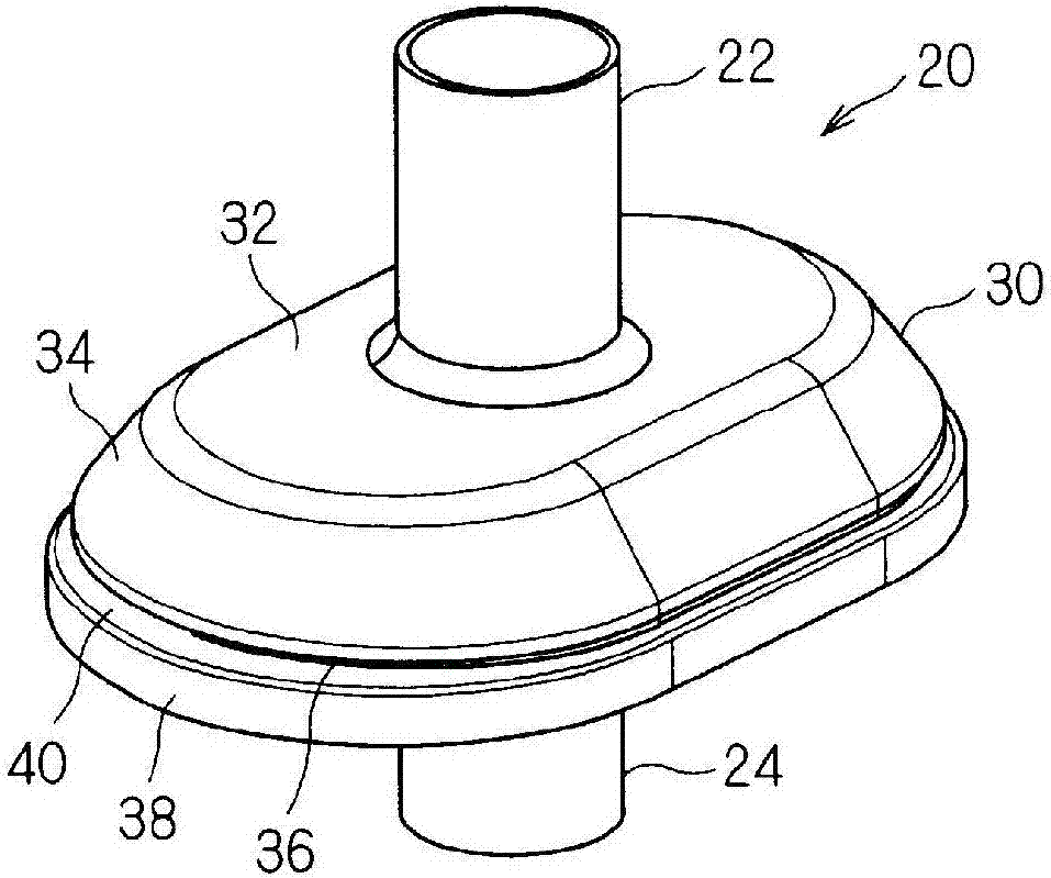
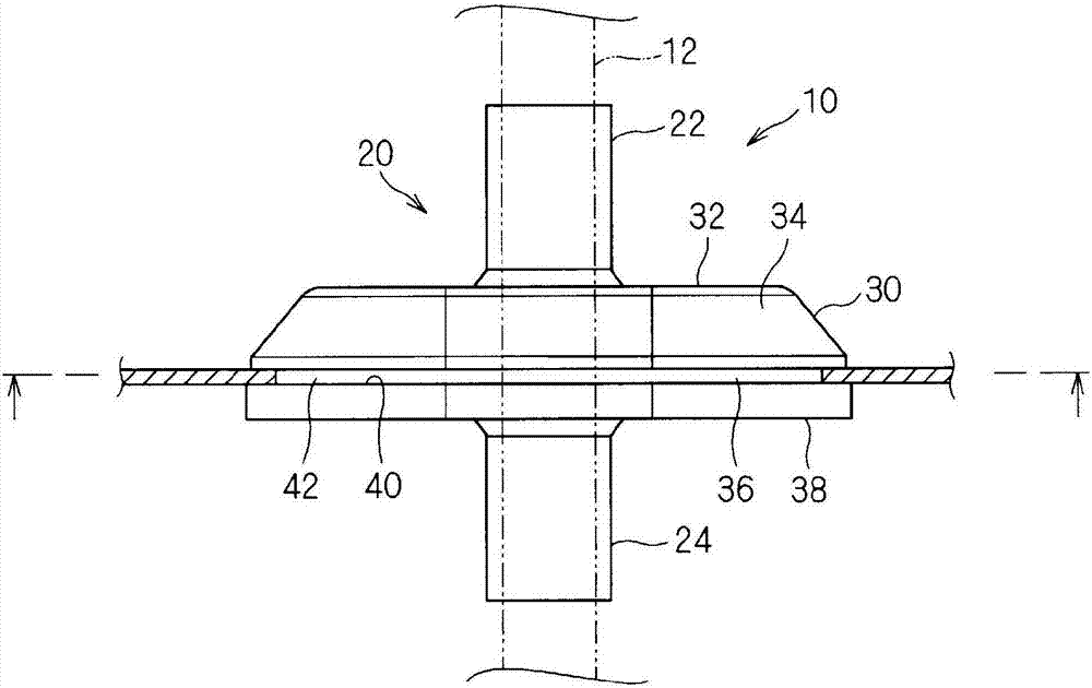
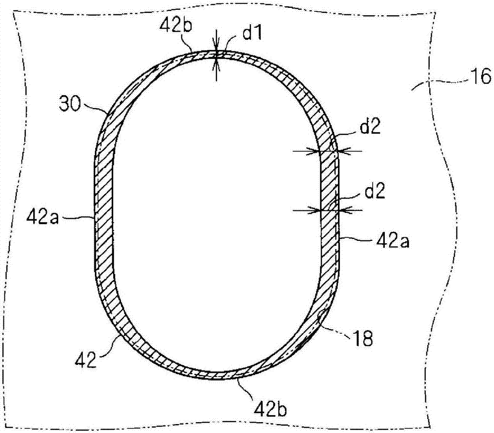
[0028] The grommet and the electric wire with the grommet according to the embodiment will be described below. figure 1 is a perspective view showing the grommet 20, figure 2 It is a schematic side view showing the state where the electric wire 10 with a grommet is attached to the panel 16 (that is, the attachment structure of the grommet for the electric wire 10 with a grommet). in addition, image 3 It shows the state in which the mounting portion 30 is projected onto the peripheral portion of the through hole 18 of the panel 16 with a cross-sectional shape perpendicular to its central axis (coincident with the central axis of the cylindrical portions 22 and 24 ) and cut through the plane of the annular groove 40 . In addition, in this projected state, the center of the cross-sectional shape coincides with the center of the through hole 18 .

[0029] The electric wire 10 with a grommet includes an electric wire 12 and a grommet 20 .

[0030] Here, the electric wire 10 w...


PUM


Abstract

The purpose of the present invention is to improve, in a grommet to be fitted into a track-shaped through hole, a water-stopping property between an inner circumferential edge of the through hole and a bottom surface of a ring-shaped groove of the grommet. A grommet of the present invention comprises: a cylindrical part; and a fitting part that is formed so as to protrude to an outer circumferential part of the cylindrical part and that has formed, in an outer circumferential part thereof, a ring-shaped groove into which the inner circumferential edge of the through hole can be inserted. A bottom surface of the ring-shaped groove is formed in a track shape that has a pair of straight-line portions and a pair of arc-shaped portions that are each formed in an outwardly convex arc shape and that connect the two ends on one side of the pair of straight-line portions and the two ends on the other side of the pair of straight-line portions. An inner circumferential part of each arc-shaped portion includes a part having a thickness that gradually increases from the center thereof toward connecting parts between the arc-shaped portions and the straight-line portions.

Description

technical field [0001] The present invention relates to a grommet attached to a through hole formed in a panel or the like of a vehicle. Background technique [0002] A through hole for drawing electric wires from one side to the other is formed in the panel of the vehicle, and in order to protect the electric wire from the inner peripheral edge of the through hole and prevent water from entering through the through hole, a With grommet. [0003] In the case where the through hole is formed in a rail shape and grooves corresponding to the rail shape are also formed on the outer periphery of the grommet, there is a problem that when the grommet is fitted into the through hole, the grommet A gap is likely to be generated between the through hole and the through hole. This is because the straight portion of the groove formed in the grommet is easily deformed inwardly, and as a result, a gap is formed between the straight portion of the groove and the straight portion of the p...

Claims


Application Information

Patent Timeline
Patent Type & Authority Applications(China)
IPC IPC(8): H02G3/22B60R16/02F16L5/02H01B7/00H01B7/282H01B17/58
CPCH02G3/22B60R16/0222H01B7/282B60R16/02F16L5/02H01B17/58H01B7/28
Inventor 宇治田智
Owner SUMITOMO WIRING SYST LTD
Why Eureka
Try Eureka