
LED light bar and LED area source module

A technology of LED light strips and photoluminescent materials, which is applied in the direction of electric light sources, lighting devices, lighting and heating equipment, etc., and can solve the problems of low luminous efficiency and uneven luminescence

Pending Publication Date: 2017-07-28
TCL VERY LIGHTING TECH HUIZHOU CO LTD +1
View PDF0 Cites 3 Cited by
  • Summary
  • Abstract
  • Description
  • Claims
  • Application Information

AI Technical Summary

Problems solved by technology

[0004] Based on this, it is necessary to provide an LED light bar and an LED surface light source module to solve the technical problems of low luminous efficiency and uneven light emission of existing LED light bars.

Method used


Image

  • LED light bar and LED area source module
  • LED light bar and LED area source module
  • LED light bar and LED area source module

Examples


Embodiment Construction

[0023] In order to make the above-mentioned objects, features and advantages of the present invention more obvious and understandable, the specific embodiments of the present invention will be described in detail below with reference to the accompanying drawings. In the following description, many specific details are explained in order to fully understand the present invention. However, the present invention can be implemented in many other ways different from those described herein, and those skilled in the art can make similar improvements without departing from the connotation of the present invention. Therefore, the present invention is not limited by the specific embodiments disclosed below.

[0024] In addition, the terms "first" and "second" are only used for descriptive purposes, and cannot be understood as indicating or implying relative importance or implicitly indicating the number of indicated technical features. Therefore, the features defined with "first" and "seco...


PUM


Abstract

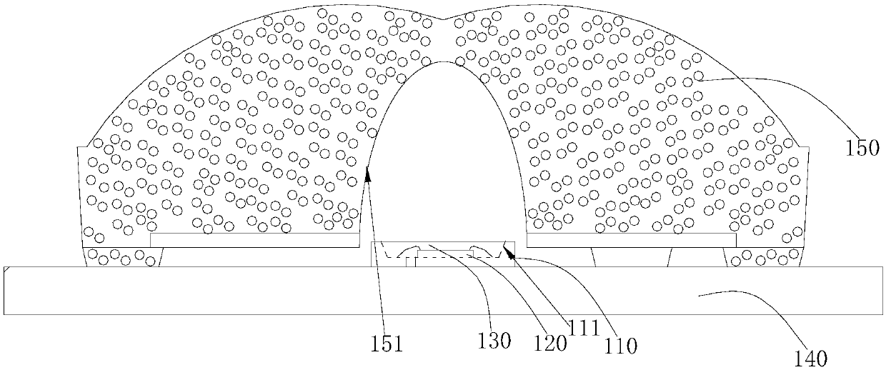
An LED light bar comprises a support, an LED wafer and a PCB, the LED wafer is fixedly arranged on the support, and the support is fixedly arranged on the PCB. The LED light bar also comprises a lens in which a photoluminescent material is arranged, and the LED wafer emits light via the lens. The present invention also discloses an LED area source module comprising the above LED light bar. According to the above LED light bar and the LED area source module, and by arranging the photoluminescent material in the lens, the diffusion range of the photoluminescent material is increased substantially, the luminescent efficiency of the LED light bar and the LED area source module is improved, and the LED light bar and the LED area source module emits light uniformly.

Description

Technical field [0001] The present invention relates to the field of LED technology, in particular to an LED light bar and an LED surface light source module. Background technique [0002] With the development of LED technology, LEDs are increasingly used in lighting and TV backlighting. At present, the main process method for preparing LED light bars is: white light LED light beads are bonded to the PCB board by reflow soldering, and the white light LED light beads are pasted on the top of the white light LED lamp beads to make the light bar, and then matched with the back plate, reflector, and diffuser. Plates, optical films, etc. constitute modules. Common white LED lamp beads realize white light emission through the LED chip in the LED lamp beads and the photoluminescent material encapsulated in the bracket. [0003] The photoluminescent material is encapsulated in the bracket. Due to the limited volume of the bracket, when the photoluminescent material and glue are mixed and...

Claims


Application Information

Patent Timeline
IPC IPC(8): H01L33/52H01L33/62H01L33/56H01L33/58F21S4/20
CPCH01L33/52H01L33/56H01L33/58H01L33/62H01L2933/0091
Inventor 胡昌志张国波
Owner TCL VERY LIGHTING TECH HUIZHOU CO LTD
Learn More