
Micro-moving position-limiting general switch

A limit and switch technology, applied in the field of micro-motion limit general switches, can solve problems such as switch signal flicker, reduce friction, have wide application prospects, and meet the needs of industry use.

Active Publication Date: 2017-07-28
ZHANGZHOU JUANMEI ELECTRIC TECH CO LTD
View PDF5 Cites 4 Cited by
  • Summary
  • Abstract
  • Description
  • Claims
  • Application Information

AI Technical Summary

Problems solved by technology

[0008] Purpose of the invention: The purpose of the present invention is to provide a micro-movement limit universal switch that can solve the phenomenon of flickering of the switch signal caused by the failure of power or the poor contact between the dynamic and static contacts caused by the force balance state during the switch switching process

Method used


Image

  • Micro-moving position-limiting general switch
  • Micro-moving position-limiting general switch
  • Micro-moving position-limiting general switch

Examples


Embodiment 1

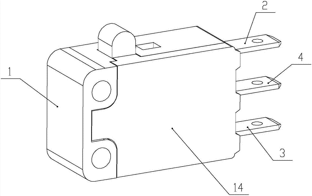
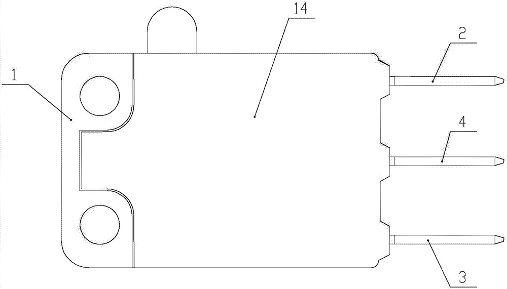
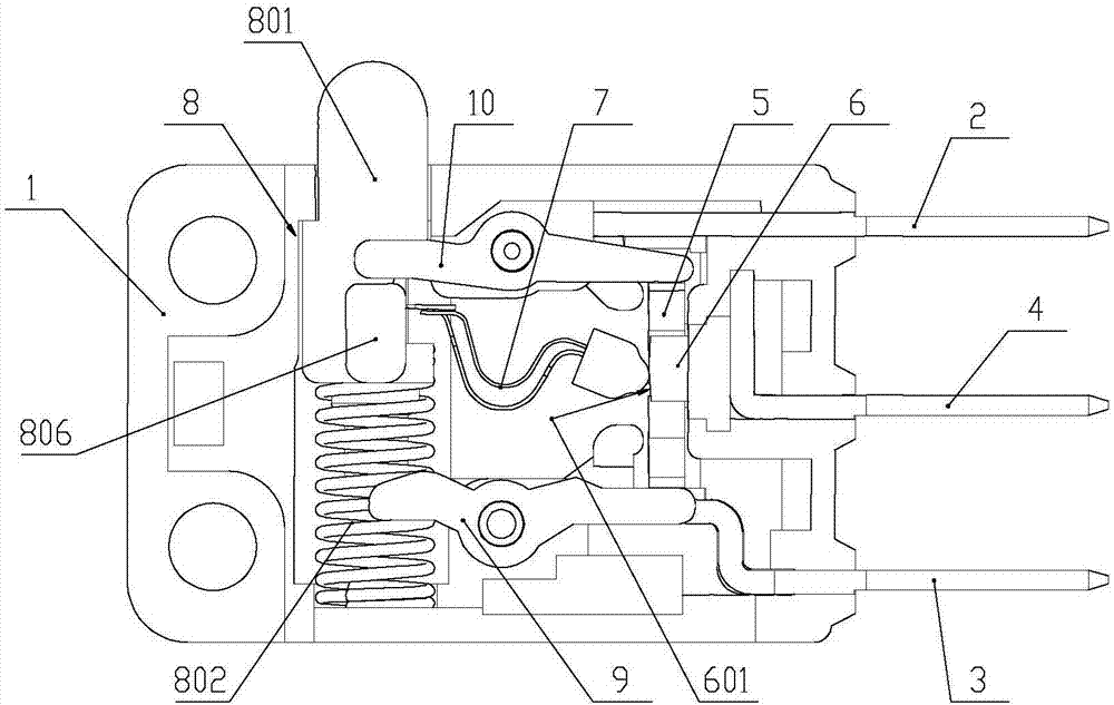
[0068] Such as figure 1 , figure 2 and image 3 As shown, in this embodiment 1, one end of the normally open connector 2, the normally closed connector 3 and the common connector 4 is located in the housing 1, and the other end extends out of the housing as a switch terminal, and the normally open connector 2, The normally closed connectors 3 are respectively provided with static contacts for conducting with the movable contacts 5 . The normally open connector 2, the normally closed connector 3 and the common connector 4 are located on the right side of the housing 1 in parallel, the common connector 4 is located between the normally open connector 2 and the normally closed connector 3, and the normally open connector 2 The left end is provided with a normally open contact located above the movable contact piece 5, which is used to realize conduction or disconnection with the movable contact piece 5; the left end of the normally closed connector 3 is provided with a normall...

Embodiment 2

[0078] Such as Figure 19 , Figure 20 and Figure 21 As shown, the general switch of the present embodiment 2 includes a housing 1 and a cover 14 adapted to the housing 1, and the housing is provided with a normally open connector 2, a normally closed connector 3, a common connector 4, The moving contact piece 5, the guide assembly 6, the elastic assembly 7 and the trigger assembly 8. One end of the normally open connector 2 and the common connector 4 protrudes from the same side of the housing as a plug terminal, and the other end of the normally open connector 2 and the common connector 4 is located in the housing 1, and the normally open connector 2 has a normally open contact for conducting or disconnecting with the movable contact piece 5. One end of the normally closed connector 3 is located in the housing 1, and has a normally closed contact on it for conducting or disconnecting with the movable contact piece 5, and the other end protrudes from one side of the housi...

Embodiment 3

[0086] Such as Figure 19 and Figure 20 As shown, the universal switch of the present embodiment 3 includes a housing 1 and a cover 14 adapted to the housing 1, and the housing is provided with a normally open connector 2, a normally closed connector 3, a common connector 4, The moving contact piece 5, the guide assembly 6, the elastic assembly 7 and the trigger assembly 8. Such as Figure 35 As shown, in the present invention, one end of the normally open connector 2 and the common connector 4 protrudes from the same side of the housing as a plug terminal, and the other end of the normally open connector 2 and the common connector 4 is located in the housing 1, And the normally open connector 2 has a normally open contact for conducting or disconnecting with the movable contact piece 5 . One end of the normally closed connector 3 is located in the housing 1, which has a normally closed contact for conducting or disconnecting with the movable contact piece 5, and the other...


PUM


Abstract

The invention discloses a micro-moving position-limiting general switch, which comprises a housing. The housing is provided therein with a normally open insertion component whose one end extends out of the housing, a normally closed insertion component and a common insertion component. The housing is also provided with a moveable contact sheet in electrical connection with the common insertion component, arranged between the static contact points of the normally open insertion component and the normally closed insertion component for switched communications and a direction guiding component used to limit the moving trajectory of the moveable contact sheet. The moveable contact sheet is connected in sequence with an elastic component and a trigger component that produce the elastic force to drive the moveable contact sheet to move. The elastic component is provided with an arc contact surface in contact with the inclined surface of the direction guiding component. According to the invention, the micro-moving position-limiting general switch adopts an elastic component to serve as the drive of the switch by producing elastic force to realize the switching of the switch, and during the switching process, downward pressure generated between the arc contact surface and the inclined surface of the direction guiding component acts on the moveable contact sheet, which avoids the occurrence of force balance by the moveable contact sheet from the transient time jumping from the normal open to the normal closed or from the normal closed to the normal open, which leads to the micro-moving and the flashing or power-off of the switch.

Description

technical field [0001] The invention relates to a switch, in particular to a universal switch with micro-motion limit. Background technique [0002] The micro switch is a contact mechanism with a small contact interval and a quick-action mechanism, which performs switching actions with a specified stroke and a specified force. It is covered with a casing and has a trigger rod on the outside. Small, hence the name micro switch. The external mechanical force acts on the action reed through the transmission element (press pin, button, lever, roller, etc.). Click on or off quickly. When the force on the transmission element is removed, the action reed produces a reverse action force, and when the reverse stroke of the transmission element reaches the action critical point of the reed, the reverse action is completed instantaneously. The contact spacing of the micro switch is small, the action stroke is short, the pressing force is small, and the on-off is rapid. The action s...

Claims


Application Information

Patent Timeline
Patent Type & Authority Applications(China)
IPC IPC(8): H01H13/52H01H13/20H01H1/50H01H1/58
CPCH01H1/50H01H1/5866H01H13/20H01H13/52
Inventor 戴四川
Owner ZHANGZHOU JUANMEI ELECTRIC TECH CO LTD
Learn More