
Internal stress measurement system and method for material based on photothermal radiation measurement

A measurement system, photothermal radiation technology, applied in the direction of measuring devices, analyzing materials, and using stable tension/pressure to test the strength of materials, etc., can solve the problems of low detection efficiency, expensive equipment detection accuracy, small material size, etc., to achieve Improve characteristic properties, completely non-destructive and non-contact measurement, and improve the effect of signal-to-noise ratio

Active Publication Date: 2017-07-28
HARBIN INST OF TECH
View PDF6 Cites 4 Cited by
  • Summary
  • Abstract
  • Description
  • Claims
  • Application Information

AI Technical Summary

Problems solved by technology

At present, for the internal stress detection methods of materials, such as nano-indentation method, ray diffraction method and drilling method, there are defects such as small material size, low detection efficiency, expensive equipment and poor detection accuracy.

Method used


Image

  • Internal stress measurement system and method for material based on photothermal radiation measurement

Examples


specific Embodiment approach 1

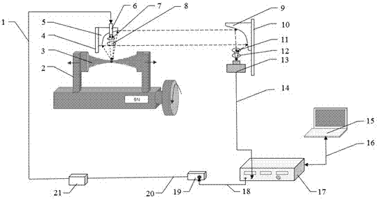
[0033] Specific implementation mode one: as figure 1 As shown, the material internal stress measurement system based on photothermal radiation measurement provided in this embodiment consists of an optical fiber 1, a manual stretching machine 2, a test sample 3, a small off-axis parabolic mirror holder 4, a small off-axis parabolic mirror 5, a quasi- Straight mirror 6, focusing mirror 7, first polarizer 8, large off-axis parabolic mirror 9, large off-axis parabolic mirror frame 10, filter 11, second polarizer 12, infrared detector (HCT, response range, 2~ 14μm) 13, the first BNC data line 14, computer 15, NI data line 16, lock-in amplifier (SR830) 17, the second BNC data line 18, 808nm laser power supply (peak power 120mW) 19, laser power supply line 20, 808nm The laser 21 is composed of a small off-axis parabolic mirror 5 installed on a small off-axis parabolic mirror holder 4, the test sample 3 is clamped on the manual stretching machine 2, the focusing mirror 7 and the firs...

specific Embodiment approach 2

[0046] Specific implementation mode 2: In this implementation mode, the test material is an aviation aluminum alloy, and the calibration sample is an aviation aluminum alloy material that has undergone aging treatment. . The steps to measure the internal stress of the material are as follows:

[0047] (1) Firstly, the calibration sample is clamped on the manual stretching machine 2 as the test sample 3, and the tension of the manual stretching machine 2 is 0 at this time;

[0048] (2) Turn on the material internal stress measurement system based on photothermal radiation measurement, this step includes turning on the computer 15, the lock-in amplifier 17, the laser power supply 19 and other equipment;

[0049] (3) The computer 15 controls the lock-in amplifier 17 and then controls the 808 nm laser 21 to emit laser light, and the power of the 808 nm laser power supply 19 is set to 20 mW;

[0050] (4) Adjust the small off-axis parabolic mirror holder 4 to focus the laser on th...


PUM


Abstract

The invention discloses an internal stress measurement system and method for material based on photothermal radiation measurement. The measurement system comprises an optical fiber, a manual drawing machine, a detecting sample, a small off-axis parabolic mirror frame, a small off-axis parabolic mirror, a collimator, a focusing mirror, a first polaroid, a large off-axis parabolic mirror, a large off-axis parabolic mirror frame, a filter, a second polaroid, an infrared detector, a first BNC data line, a computer, a NI data line, a lock-in amplifier, a second BNC data line, a laser power source, a laser power line, and a laser. The system and method measure the internal stress of the material by using the contact between the internal stress of the material and the existence of a thermal wave signal under the action of an external modulated thermal load, and is suitable for the internal stress testing of the material (metal material, composite material, inorganic non-metallic material and synthetic material).

Description

technical field [0001] The invention relates to a material internal stress measurement system and method, in particular to a material internal stress measurement system and method based on photothermal radiation measurement. Background technique [0002] With the continuous development of industrial modernization technology, the requirements for the performance and quality assurance of materials are becoming more and more stringent. Due to the unqualified processing technology or the influence of material properties, there is internal stress in the final parts or components, which seriously affects the subsequent assembly process and final use of the entire machine. Internal stress refers to the stress that remains inside the object after the external load is removed. It is caused by the inhomogeneous volume change of the macroscopic or microscopic structure inside the material. The existence of internal stress in materials has a great influence on the fatigue strength, st...

Claims


Application Information

Patent Timeline
Patent Type & Authority Applications(China)
IPC IPC(8): G01L5/00G01N3/06G01N3/08
CPCG01L5/0047G01N3/068G01N3/08
Inventor 刘俊岩王飞宋鹏冀嘉琦林裕山王扬
Owner HARBIN INST OF TECH
Learn More