Environmental protection equipment

A kind of environmental protection equipment and sliding technology, applied in the direction of chemical instruments and methods, cleaning methods and utensils, cleaning methods using liquids, etc., can solve the problems of not having fixed workpieces, affecting the cleaning process, and not having emergency stop for flushing nozzles, etc. , to achieve the effects of simple structure, convenient movement and handling, improved flushing efficiency and flushing accuracy

Inactive Publication Date: 2017-07-28
SUZHOU HUANZHIDAO INTELLIGENT TECH CO LTD
View PDF1 Cites 5 Cited by
  • Summary
  • Abstract
  • Description
  • Claims
  • Application Information

AI Technical Summary

Problems solved by technology

However, the current cleaning machines generally do not have the function of fixing the workpiece. When the workpiece is not heavy, it is easily washed away by the water column, which affects the normal cleaning process.
At the same time, the nozzles of the existing flushing machines do not rotate during the flushing process, and the flushing area is small. Some of the flushing nozzles that can be rotated do not have the function of emergency stop and cannot meet the needs.

Method used


Image

  • Environmental protection equipment
  • Environmental protection equipment
  • Environmental protection equipment

Examples


Embodiment Construction

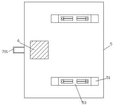
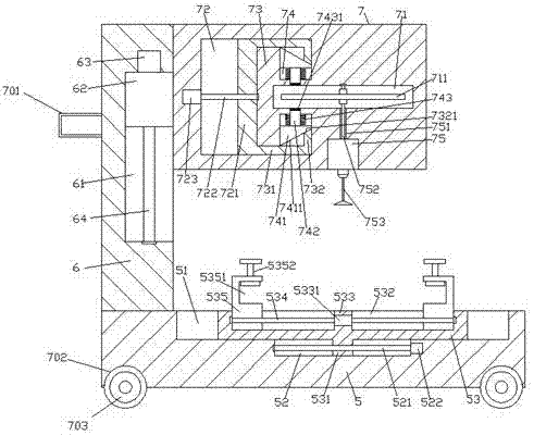
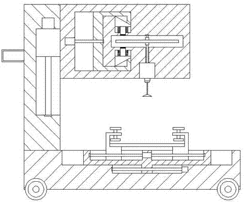
[0022] Such as Figure 1-Figure 5 As shown, an environmental protection equipment of the present invention includes a base 5 and a flushing structure 7 arranged above the top of the base 5, a support column 6 is provided on the top surface of the left side of the base 5, and the base 5 The top surface of the left side is provided with first sliding grooves 51 front and rear opposite to each other. The center of the inner bottom surface of each first sliding groove 51 is provided with a second sliding groove 52. The second sliding groove 52 is provided with left and right sliding grooves. The first screw rod 521 is extended, the first sliding block 53 is slidingly connected in the first sliding groove 51, the flushing structure 7 is provided with a sliding cavity 72, and the sliding cavity 72 A convex portion 73 is provided inside the right side, and a locking cavity 71 extending to the right is provided in the convex portion 73. A flushing motor 75 is fixedly arranged in the bo...


PUM


Abstract

The invention discloses an environmental protection device, which comprises a machine base and a flushing structure arranged above the top of the machine base, a support column is arranged on the top surface of the left side of the machine base, and a first sliding groove is arranged opposite to the front and rear on the left side top surface of the machine base , the center of the inner bottom surface of each first sliding groove is provided with a second sliding groove, and the second sliding groove is provided with a first screw rod extending left and right, and the first sliding groove is connected with a first sliding groove. The sliding block has a sliding cavity inside the flushing structure, a convex part inside the right side of the sliding cavity, a locking cavity extending to the right inside the convex part, and a flushing motor fixed on the bottom surface of the flushing structure. The bottom of the flushing motor is connected with a flushing head, and a through hole is arranged between the top of the flushing motor and the bottom of the locking cavity, and a rotating shaft extending up and down is connected in the through hole; the invention has simple structure, high safety, and improves the flushing efficiency and flushing accuracy.

Description

Technical field [0001] The invention relates to the field of environmental protection, in particular to an environmental protection device. Background technique [0002] In the production process of industrial production and electronic products, the surface of the workpiece will be stained with oil, wax, dust, oxide layer and other stains and stains, and the selection of washing can peel off and wash away the dirt, which is economical and environmentally friendly, and can effectively clean the dirt. However, the current cleaning machine generally does not have the function of fixing the workpiece. When the workpiece is not heavy, it is easily washed away by the water column, which affects the normal cleaning process. At the same time, the nozzle of the existing washing machine does not rotate during the washing process, the washing area is small, and some of the rotating washing nozzles do not have the function of emergency stop and cannot meet the demand. Summary of the inventi...

Claims


Application Information

Patent Timeline
IPC IPC(8): B08B3/02
CPCB08B3/02
Inventor 张明
Owner SUZHOU HUANZHIDAO INTELLIGENT TECH CO LTD
Why Eureka
Try Eureka