
Loudspeaker box

A speaker box and basin frame technology, which is applied in the field of acoustics and electricity, can solve the problems of occupying volume, not being able to fill the whole cavity and half of the cavity at the same time, and the filling volume cannot be maximized, etc., to achieve improved audio performance, simple structure, and improved The effect of low frequency performance

Inactive Publication Date: 2017-07-25
AAC TECH PTE LTD
View PDF6 Cites 19 Cited by
  • Summary
  • Abstract
  • Description
  • Claims
  • Application Information

AI Technical Summary

Problems solved by technology

[0006] However, the speaker box of the related art, especially the semi-open speaker box, that is, a part of the back cavity is directly connected with the outside world, and the back cavity is divided into a full cavity part and a half cavity part connected with the full cavity part, so The loudspeaker is installed in the half-cavity. When a virtual acoustic cavity is formed, only the full-cavity or a part of the half-cavity can be filled with sound-absorbing materials, and the connected full-cavity and half-cavity cannot be filled with sound-absorbing materials. The part is filled with particles at the same time; and when the full cavity is filled with particles, an additional breathable spacer is required to prevent the particles from entering the half cavity and affecting the sound of the speaker. Because the space occupied by the breathable spacer results in the filling volume not being maximized, Audio performance improvements are limited

Method used


Image

  • Loudspeaker box
  • Loudspeaker box
  • Loudspeaker box

Examples


Embodiment Construction

[0028] The following will clearly and completely describe the technical solutions in the embodiments of the present invention with reference to the accompanying drawings in the embodiments of the present invention. Obviously, the described embodiments are only some, not all, embodiments of the present invention. Based on the embodiments of the present invention, all other embodiments obtained by persons of ordinary skill in the art without making creative efforts belong to the protection scope of the present invention.

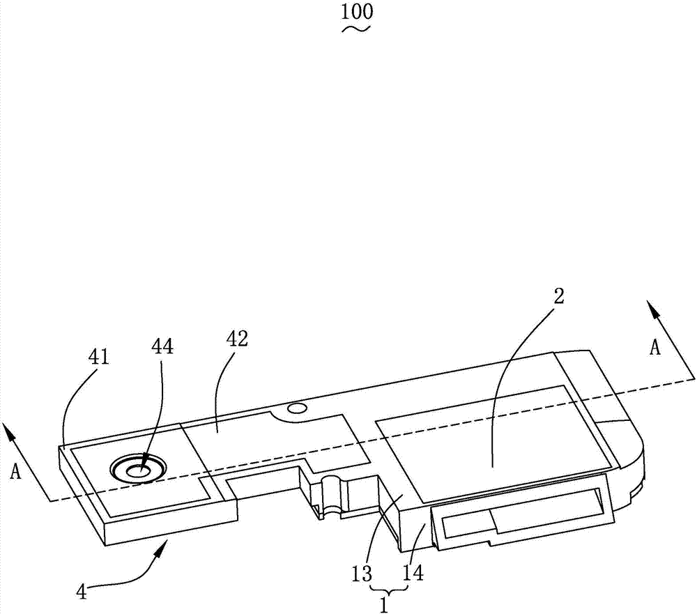
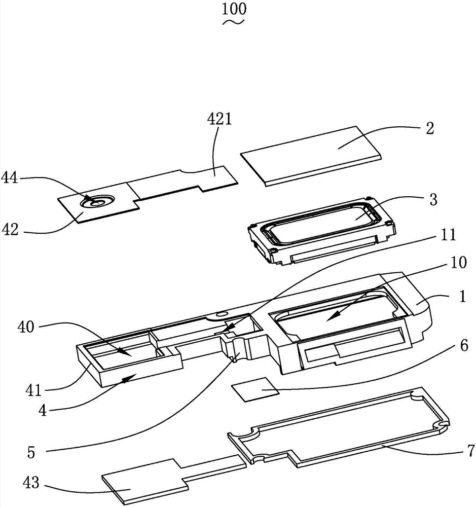
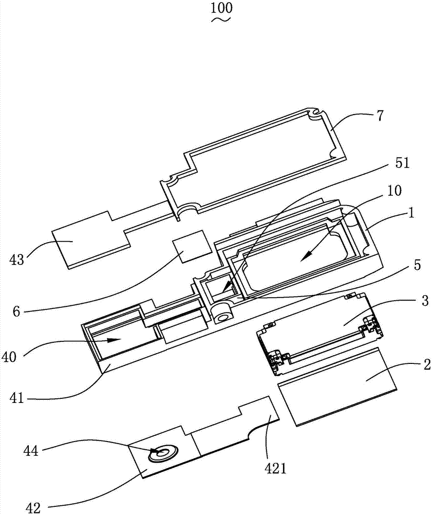
[0029] see Figure 1-3 ,in, figure 1 It is a schematic diagram of the three-dimensional structure of the speaker box of the present invention; figure 2 for figure 1 The exploded view of the three-dimensional structure; image 3 for figure 1 An exploded view of the three-dimensional structure from another perspective. The present invention provides a speaker box 100 , which includes a main frame 1 , a first upper cover 2 , a sound emitting unit 3 , an ext...


PUM


Abstract

The invention provides a loudspeaker box comprising a main cone frame, a first upper cover covered on a top end of the main cone frame and enclosed to form an accommodation space together with the main cone frame, and a sound production monomer accommodated in the accommodation space, wherein the sound production monomer and the first upper cover are enclosed to form a front cavity together, the sound production monomer and the main cone frame are enclosed to form a back cavity together, the loudspeaker box further comprises an extension part extending from the main cone frame toward a direction away from the accommodation space, a trunk bulkhead extending from the top end toward the bottom end of the main cone frame and a ventilating isolation part; a first sound absorption cavity filled with a sound production material is arranged in the extension part; the trunk bulkhead is located in the back cavity and is enclosed to form a second sound absorption cavity for accommodating the sound production material together with the main cone frame; the first sound absorption cavity communicates with the second sound absorption cavity, and the second sound absorption cavity communicates with the back cavity; and the ventilating isolation part is covered on one end of the second sound absorption cavity away from the first upper cover so as to prevent the sound production material from entering the back cavity. Compared with the prior art, the loudspeaker provided by the invention has the advantages of simple structure, and good low audio performance, and especially low frequency performance.

Description

[0001] 【Technical field】 [0002] The invention relates to the field of sound and electricity, in particular to a speaker box applied to portable electronic products. [0003] 【Background technique】 [0004] With the advent of the mobile Internet era, the number of smart mobile devices continues to rise. Among the many mobile devices, the mobile phone is undoubtedly the most common and portable mobile terminal device. At present, the functions of mobile phones are extremely diverse, one of which is the function of high-quality music. Therefore, speakers for playing sound are widely used in current smart mobile devices. [0005] In order to increase the acoustic performance of the existing speakers, especially the low-frequency performance, the speakers are usually installed in a box to form a speaker box, and a part of the speaker box is used to install the speakers and jointly form a front cavity. The other part is used to form the back cavity. The rear cavity is filled wit...

Claims


Application Information

Patent Timeline
IPC IPC(8): H04R9/06H04R9/02H04R1/02
CPCH04R9/06H04R1/025H04R9/02H04R2400/11
Inventor 印兆宇
Owner AAC TECH PTE LTD
Learn More