
Aeration sustained-release device

A slow-release device and aeration technology, applied in aerobic process treatment, sustainable biological treatment and other directions, can solve the problems of aeration tank generation, hole blockage of air trapping plate, time-consuming and laborious moss, etc., to achieve high-efficiency metabolism, The effect of improving water quality and improving accuracy

Active Publication Date: 2017-07-25
BIOGAS SCI RES INST MIN OF AGRI
View PDF12 Cites 1 Cited by
  • Summary
  • Abstract
  • Description
  • Claims
  • Application Information

AI Technical Summary

Problems solved by technology

[0005] 1. The top of a micro-dynamic slow-release aeration structure is a closed design, and the aeration tank needs to be cleaned after running for a certain period of time. The sealed design is not easy to clean. If the aeration tank is not cleaned for a long time, it will cause the surface of the aeration tank to Generate a lot of air bubbles and suspended matter
[0006] 2. During the long-term use of the air trapping disc, the suspended solids in the aeration tank will adhere to it, which will block the holes of the air trapping disc and affect the use
[0007] The existing open aeration tank, after running for a period of time, moss often grows on the pool wall. Manual treatment of moss is not only time-consuming and laborious, but adding chemicals will also affect the amount of microbial cells in the aeration tank

Method used


Image

  • Aeration sustained-release device
  • Aeration sustained-release device
  • Aeration sustained-release device

Examples


Embodiment 1

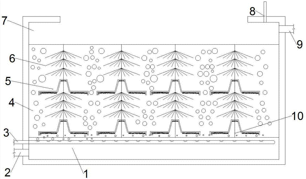
[0023] The aeration slow-release device includes a water outlet layer 1, a water outlet pipe 2, an aeration pipe 3, an aeration layer 4, a slow-release device 5, a microorganism-adhered umbrella fiber 6, a water inlet layer 7, an air outlet pipe 8, and a water inlet pipe 9. Rope10.

[0024] The outlet pipe 2 is connected to the water outlet layer 1, the aeration pipe 3 is arranged in the water outlet layer 1, and the aeration layer 4 is arranged on the upper side of the water outlet layer 1; a rope 10 is arranged in the aeration layer 4, and the rope 10 is installed There are slow-release devices 5 and umbrella fibers 6 attached to microorganisms, and the water inlet layer 7 is arranged on the upper side of the aeration layer 4;

[0025] Preferably, on the said rope 10, every 3 microbial attachment umbrella fibers 6 are provided with a slow release device 5, which optimizes the configuration. If the number of microbial attachment umbrella fibers 6 is more than the set value, t...

Embodiment 2

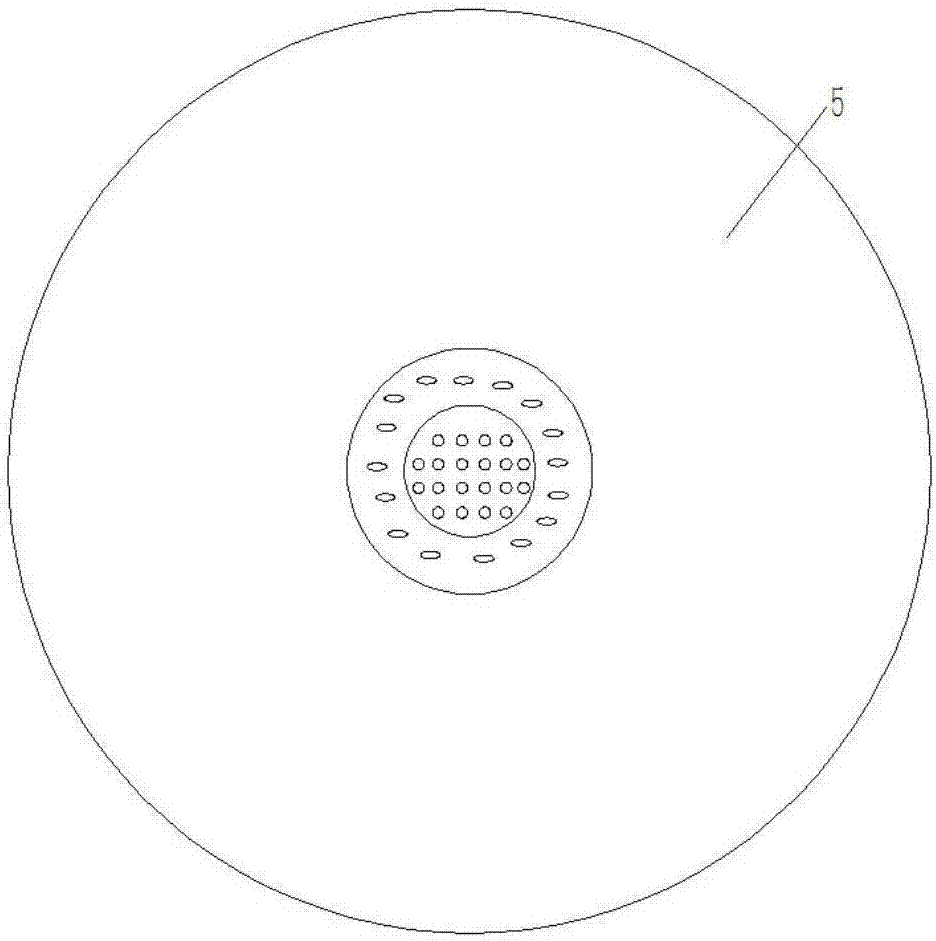
[0038] Such as figure 1 , Figure 4 As shown, the difference between embodiment 2 and embodiment 1 lies in that the structure of the slow-release device is different from that of embodiment 1.

[0039] The slow-release device 5 includes a left grip, a left arm, a left rib, a connecting plate, a right rib, a right arm, and a right grip. The left grip is connected to the left arm, the left arm is connected to the left rib, and the left rib is connected to The board is connected to the right rib, the right rib is connected to the right arm, and the right arm is connected to the right grasp.

[0040] Further, the left rib is provided with a left rib vent hole, the connecting plate is provided with a connecting plate vent hole, the right rib is provided with a right rib vent hole, and the connecting plate is provided with a connecting plate vent hole, which The density of the holes is greater than the density of the vent holes of the left rib on the left rib and the density of th...

Embodiment 3

[0043] Such as figure 1 , Figure 5As shown, the difference between embodiment 3 and embodiment 1 is that the sustained release device 5 in embodiment 3 is made of ceramics.

[0044] The slow-release device in Example 3 is porous ceramics, which can reduce the attachment of suspended particles in the sewage by adopting ceramics, wherein the raised top surface and surrounding edge holes are through holes, while the rest are blind holes, and the size of the holes is inconsistent. After the aeration tube 3 stops working, the slow release device 5 can collect a part of the gas, and the gas is discharged from the through hole.

[0045] Working process of the present invention:

[0046] The water to be treated enters the water inlet layer 7 from the water inlet pipe 9, and the air is introduced into the aeration pipe 3 to start aeration. When the aeration rate is sufficient, the microorganisms attached to the umbrella fiber 6 can remove the bacteria in the water body. Organic mat...


PUM

PropertyMeasurementUnit
The inside diameter ofaaaaaaaaaa
Diameteraaaaaaaaaa

Abstract

The invention relates to an aeration sustained-release device, belonging to the technical field of sewage treatment. The aeration sustained-release device comprises a water outlet layer (1), a water outlet pipe (2), an aeration pipe (3), an aeration layer (4), sustained-release devices (5), microorganism attachment umbrella fibers (6), a water inlet layer (7), an air outlet pipe (8), a water inlet pipe (9) and ropes (10), wherein the water outlet pipe (2) is connected with the water outlet layer (1); the aeration pipe (3) is arranged in the water outlet layer (1), and the aeration layer (4) is arranged at the upper side of the water outlet layer (1); the aeration layer (4) is internally provided with the ropes (10), and the sustained-release devices (5) and the microorganism attachment umbrella fibers (6) are installed on the ropes (10); the water inlet layer (7) is arranged at the upper side of the aeration layer (4); the air outlet pipe (8) is connected with the water inlet layer (7); the water inlet pipe (9) is connected with the water inlet layer. The aeration sustained-release device is capable of realizing extended aeration according to the need, thus reducing the energy consumption; furthermore, the aeration sustained-release device convenient and simple to install.

Description

technical field [0001] The invention belongs to the technical field of sewage treatment and purification, and in particular relates to an aeration slow-release device. Background technique [0002] Invention name A multi-stage fiber packing device for biological aerated filter, application number 201611021687.2, discloses a device that uses multi-stage fiber bundle packing to intercept nanometer or even smaller particles in sewage, which can classify sewage Filtering and intercepting particulate matter can achieve different levels of sewage treatment with high purification efficiency, but it fails to optimize the aeration process. [0003] Microorganisms are attached to the fibers in the water body. Excessive aeration not only wastes energy, but also causes a large number of aerobic respiration filamentous bacteria in the water, which makes it difficult to settle the sludge in the post-treatment process; concentration of domestic sewage, making it unable to meet the sewage ...

Claims


Application Information

Patent Timeline
IPC IPC(8): C02F3/02
CPCC02F3/02Y02W10/10
Inventor 潘科施国中陈子爱何明雄汤晓玉张敏
Owner BIOGAS SCI RES INST MIN OF AGRI
Learn More