Eureka AIR delivers breakthrough ideas for toughest innovation challenges, trusted by R&D personnel around the world.

Sizing agent discharging device

A feeder and slurry technology, which is applied in the field of slurry filling devices, can solve problems such as difficulty in grasping, waste, and test errors, and achieve the effect of preventing insufficient addition amount and avoiding waste

Inactive Publication Date: 2017-07-25
ZHENGZHOU UNIV +1
View PDF7 Cites 0 Cited by
  • Summary
  • Abstract
  • Description
  • Claims
  • Application Information

AI Technical Summary

Problems solved by technology

However, if the feeding equipment and operation methods used are not uniform, such as using funnels of different sizes or shovels of different sizes for perfusion feeding, or the distance between the mouth of the funnel or the shovel and the simulated crack opening is different due to human factors Both directly affect the accuracy of the test results. At the same time, due to the differences in the consistency and viscosity of the various grouting materials in the comparative test, feeding devices of different specifications are required, which increases the cost and brings inconvenience to the operation.
In addition, it is not easy to grasp how much grouting material needs to be added in the grout feeder. Adding too much will cause waste, adding too little will not fill the simulated cracks, and refilling will cause test errors or even lead to test failure.

Method used


Image

  • Sizing agent discharging device
  • Sizing agent discharging device

Examples


Embodiment Construction

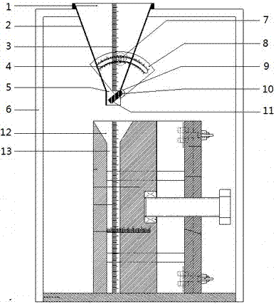
[0015] A slurry feeder, such as Figure 1-2 As shown, it includes a barrel 2 with a feed port 1 and a discharge port 5, a gate 11 for adjusting the opening of the discharge port 5, a gate shaft 10, a shaft sleeve 9, a turntable 8, and a turntable tightening screw 7 And the bracket 6, the barrel 2 is an inverted truncated cone structure, the discharge port 5 of the barrel 2 is a rectangular structure extending in the front and rear directions, and the length of the discharge port 5 matches the length of the simulated crack 13. The gate 11 is located at the discharge port 5 and is arranged on the barrel 2 through the pitch and rotation of the gate shaft 10. Specifically, the shaft sleeve 9 is arranged on the front and rear outer walls of the discharge port 5, and the gate shaft 10 is rotatably inserted in In the corresponding shaft sleeve 9, the turntable 8 is fixedly arranged with the gate 11 through the gate shaft 10, the turntable 8 has an arc-shaped slot, and at least one sid...


PUM


Abstract

The invention relates to a slurry feeder, which comprises a barrel body with a material inlet and a material outlet, a gate for adjusting the opening of the material outlet, a rotating shaft of the gate, a turntable and a turntable tightening screw. The discharge port is set on the barrel body through the pitch rotation of the ram shaft, and the turntable is fixed with the ram through the ram shaft. There is an arc-shaped slot on the turntable. physically. A kind of slurry feeder of the present invention, according to the grouting materials of different properties, adjusts the opening of the discharge port by rotating the turntable to drive the shutter, and then fixes the turntable by tightening the screws of the turntable. The angle of the plate is fixed, so as to fix the opening of the discharge port, adjust the flow rate of the grouting material, ensure the flow rate is controllable, and prevent the test from failing due to too fast or too slow feeding. At the same time, the structure of the grout discharger is simple, low cost.

Description

Technical field [0001] The invention relates to a slurry pouring device, in particular to a slurry feeder. Background technique [0002] In the pourability test of concrete crack grouting material, in order to compare the pourability of different grouting materials, it is necessary to pour the grouting material into the simulated cracks, and then compare the fullness of different performance grouting materials in the simulated cracks. , Filling time and other grouting indicators, so as to evaluate the grouting ability. However, if the feeding equipment and operation methods used are not uniform, such as the use of different sizes of funnels or different sizes of shovel for filling and feeding, or the difference in the height of the hopper or the shovel opening due to human factors All directly affect the accuracy of the test results. At the same time, due to the difference in consistency and viscosity of the various grouting materials in the comparison test, different specificat...

Claims


Application Information

Patent Timeline
IPC IPC(8): B65G65/40
CPCB65G65/40
Inventor 高丹盈汤寄予钱钰钦李泽亚李庆斌何国建吕铭艳
Owner ZHENGZHOU UNIV
Why Eureka
Eureka Blog
Learn More