Traffic system capable of controlling lane direction changing

A traffic system and lane technology, which is applied in the field of traffic systems that can control lane changes, can solve problems such as expressway congestion or unreachable driving speed, safety, low implementability, waste of road resources, etc., and improve road utilization. , the effect of solving the problem of traffic congestion

Inactive Publication Date: 2017-07-21
SHENZHEN POLYTECHNIC
View PDF11 Cites 21 Cited by
  • Summary
  • Abstract
  • Description
  • Claims
  • Application Information

AI Technical Summary

Problems solved by technology

[0002] With the development of cities and the improvement of people's living standards, more and more people have purchased private cars. During holidays with a relatively long holiday, most expressways will experience a sharp increase in traffic flow in one direction and traffic in the other direction. The phenomenon that the traffic flow decreases instead leads to congestion on the expressway or the driving speed does not reach the original set speed range. In the current expressway traffic planning principle, the two-way traffic distribution on the default road is uniform, so the two-way lanes of the expressway The quantity is equal, but this is not completely consistent with the actual road conditions, and the road resources cannot be fully utilized, resulting in waste of road resources, and the problem of traffic jams cannot be effectively resolved
[0003] At present, the guardrails set between the lanes in different directions of the expressway are fixed and non-retractable, or the guardrails are moved to the other side of the lane. For example, the patent application number is: 201310067474.3. The guardrail moving method invented by this patent is ambiguous The instructions stated that the guardrail is moved to the other side of the lane, and the specific implementation method is not described, and the guardrail is moved through the guide rail, which is low in safety and implementation

Method used


Image

  • Traffic system capable of controlling lane direction changing
  • Traffic system capable of controlling lane direction changing
  • Traffic system capable of controlling lane direction changing

Examples


Embodiment Construction

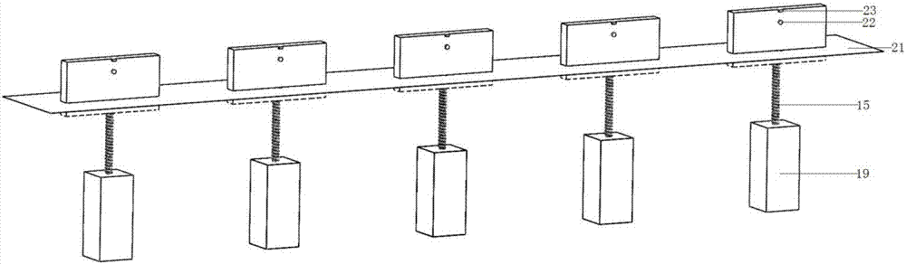
[0030] Please refer to the accompanying drawings, a traffic system that can control lane changes, including a frame main body, a control device and a traffic management center, a guide screen 1 and a guide screen 2 are installed above the frame main body, and the guide screen 1 and the guide screen A warning light 1 and a warning light 2 are respectively installed at the bottom of the two, a horn is installed between the guide screen 1 and the guide screen 2, a camera is installed on the back of the guide screen 1 and the guide screen 2, and a camera can be installed directly below the main body of the frame. Telescopic blocking fence one and telescopic blocking fence two, the main body of the frame is installed at the entrance and exit of the driveway, a retractable device, guide light one, and guide light two are installed on the driveway, the bottom of the expandable device is connected with the screw mandrel mold group connection, and the screw module is connected to the mo...


PUM


Abstract

The invention relates to a traffic system capable of controlling lane direction changing. The traffic system is composed of main frame bodies, a control unit, and a traffic management center. The traffic system is characterized in that guide screens I and guide screens II are installed above the main frame bodies; warning lights I and warning lights II are installed correspondingly at the bottoms of the guide screens I and the guide screens II; and loudspeakers are installed between the guide screens I and the guide screens II. The main frame bodies are installed at a lane entrance and a lane exit respectively. An extension type blocking fence I, an extension type blocking fence II, guide lights I, guide lights II, and extension type guardrails are arranged at a lane; the bottoms of the extension type guardrails are connected with lead screw module groups; and the lead screw module groups are connected with motors. The traffic system has the following advantages: a traffic management center controls extension type devices remotely to change a lane indication direction according to a detected lane traffic flow change, so that dynamic adjustment of the lane function can be realized and a traffic congestion problem can be alleviated.

Description

technical field [0001] The invention relates to the technical field of road traffic, in particular to a traffic system capable of controlling lane change. Background technique [0002] With the development of cities and the improvement of people's living standards, more and more people have purchased private cars. During holidays with a relatively long holiday, most expressways will experience a sharp increase in traffic flow in one direction and traffic in the other direction. The phenomenon that the traffic flow decreases instead leads to congestion on the expressway or the driving speed does not reach the original set speed range. In the current expressway traffic planning principle, the two-way traffic distribution on the default road is uniform, so the two-way lanes of the expressway They are equal in quantity, but this is not completely consistent with the actual road conditions, and road resources cannot be fully utilized, resulting in waste of road resources, and the...

Claims


Application Information

Patent Timeline
IPC IPC(8): G08G1/08G08G1/09G08G1/065E01F15/12
CPCG08G1/08E01F15/12G08G1/065G08G1/09
Inventor 向怀坤
Owner SHENZHEN POLYTECHNIC
Why Eureka
Try Eureka