
A hydraulically driven flexible robot joint

A robot joint and flexible technology, applied in the field of bionic robots, can solve problems such as heavy weight, unfavorable robots, increased complexity and nonlinearity of motor dynamic modeling, etc., to reduce energy consumption, improve motion efficiency, and reduce overall weight Effect

Active Publication Date: 2019-01-15
HUAZHONG UNIV OF SCI & TECH
View PDF4 Cites 1 Cited by
  • Summary
  • Abstract
  • Description
  • Claims
  • Application Information

AI Technical Summary

Problems solved by technology

In terms of joint servo drives, in the past, more robots used motors as power sources, but the reducer increased the output impedance of the motor while increasing the force and energy density of the motor drive, and at the same time increased the complexity of motor dynamics modeling. Non-linearity and nonlinearity make it difficult to control the precise force of the motor driver, and also make the entire system too heavy, which is not conducive to robot walking

Method used


Image

  • A hydraulically driven flexible robot joint
  • A hydraulically driven flexible robot joint
  • A hydraulically driven flexible robot joint

Examples


Embodiment Construction

[0020] In order to make the object, technical solution and advantages of the present invention clearer, the present invention will be further described in detail below in conjunction with the accompanying drawings and embodiments. It should be understood that the specific embodiments described here are only used to explain the present invention, not to limit the present invention. In addition, the technical features involved in the various embodiments of the present invention described below can be combined with each other as long as they do not constitute a conflict with each other.

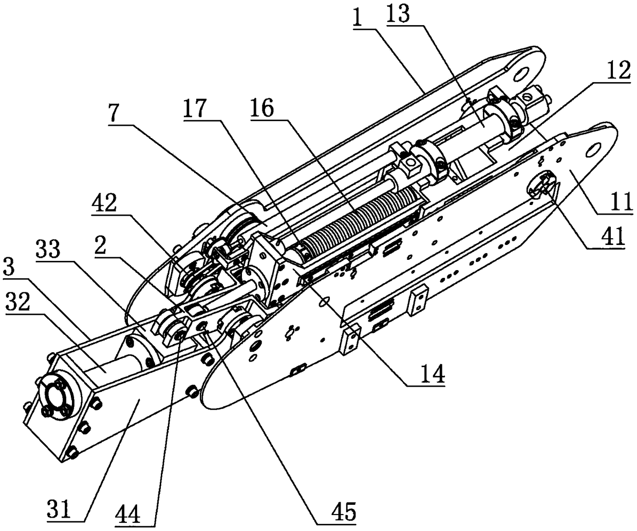
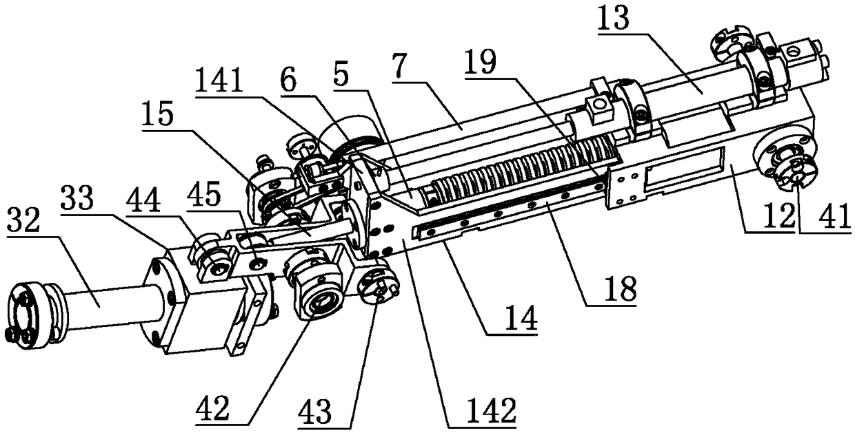
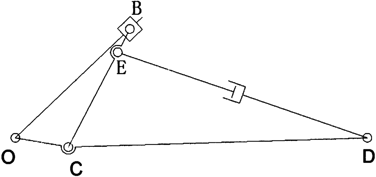
[0021] refer to Figure 1 ~ Figure 3 , a hydraulically driven flexible robot joint, including a thigh structure 1, a thigh structure 2 and a lower leg structure 3, wherein,

[0022] The thigh structure 1 includes a thigh main frame 11, a cylinder base 12, a hydraulic cylinder 13, a moving frame 14, a guide shaft 15 and a compression spring 16, and the cylinder base 12 is hinged to the thigh mai...


PUM


Abstract

The invention belongs to the field of bio-robots, and discloses a hydraulic driving flexible robot joint which comprises a thigh structure, a thigh-crus connecting frame and a crus structure. The thigh structure comprises a thigh body frame, a cylinder seat, a hydraulic cylinder, a movable frame, a guide shaft and a compression spring. The crus structure comprises a crus body frame, a guide rail and a slide block. The crus body frame is hinged to the thigh body frame. The guide rail is installed on the crus body frame. The slide block is installed on the guide rail. One end of the thigh-crus connecting frame is hinged to the thigh body frame, and the other end of the thigh-crus connecting frame is hinged to the slide block. In addition, the thigh-crus connecting frame is hinged to the end, away from the hydraulic cylinder, of the guide shaft. The hydraulic driving flexible robot joint can adapt to changes of external loads, have the bionic flexible characteristic and force arm characteristics, meet motion requirements of a robot, and can effectively reduce the total weight, achieve lightweight and improve the motion efficiency.

Description

technical field [0001] The invention belongs to the field of bionic robots, and more specifically relates to a hydraulically driven flexible robot joint. Background technique [0002] With the development of robotics technology, there are more and more types of robots, and the scope of application is wider and wider. The current robots mainly have bipedal, quadrupedal, multi-legged and other forms, but no matter what kind of robot, one of its design cannot The problem to be avoided is the design and manufacture of the joint part. The design of the joint part is directly related to the dynamic performance and walking efficiency of the whole robot, so the joint bionic drive technology has become an important research direction in the field of robotics. In terms of joint servo drives, in the past, more robots used motors as power sources, but the reducer increased the output impedance of the motor while increasing the force and energy density of the motor drive, and at the sam...

Claims


Application Information

Patent Timeline
Patent Type & Authority Patents(China)
IPC IPC(8): B62D57/032
CPCB62D57/032
Inventor 高亮唐华彬李新宇宋志涛董昊臻王美思胡成颢李硕钟浩然李星辰肖新安卢盛雨
Owner HUAZHONG UNIV OF SCI & TECH
Learn More