
A ceramic tile automatic correction device

A technology for automatic calibration and ceramic tile, applied in the direction of work accessories, manufacturing tools, stone processing tools, etc., can solve the problems of low production flexibility and adaptability, low calibration efficiency, tile damage, etc., and achieve high production flexibility and adaptability. , the effect of reducing the diagonal error and improving the correction efficiency

Active Publication Date: 2018-12-07
GUANGDONG SINID TECH
View PDF6 Cites 0 Cited by
  • Summary
  • Abstract
  • Description
  • Claims
  • Application Information

AI Technical Summary

Problems solved by technology

However, the existing correction device is to set two correction blocks on the left and right sides of the tile conveyor belt, and the tile conveyor belt needs to be stopped, and then the centering correction is performed from the left and right sides of the tiles, and only one tile can be corrected at a time , the correction efficiency is low; the two correction blocks will squeeze the tiles during correction, which is easy to cause damage to the tiles; and it cannot effectively reduce the diagonal error during edge trimming, and cannot ensure that the tiles after edge trimming are square, which gives The processing of square tiles brings trouble; there is also the existing calibration device that needs to adjust the distance between the two calibration blocks according to the size of the tiles, which has low production flexibility and adaptability

Method used


Image

  • A ceramic tile automatic correction device
  • A ceramic tile automatic correction device
  • A ceramic tile automatic correction device

Examples


Embodiment Construction

[0039] The technical solutions of the present invention will be further described below in conjunction with the accompanying drawings and through specific implementation methods.

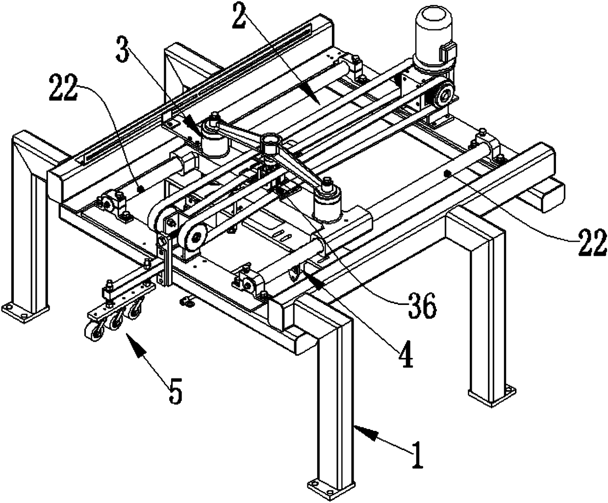
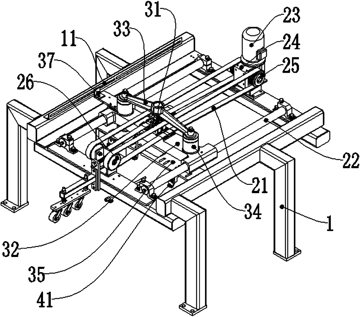
[0040] The tile automatic correction device of this embodiment, such as figure 1 As shown, it includes a brick pusher frame 1, a synchronous sliding unit 2, a brick pusher movable unit 3 and a correction block unit 4, the synchronous slide unit 2 is installed on the brick pusher frame 1, and the brick pusher movable unit 3 It is connected with the synchronous sliding unit 2, and the correction block unit 4 is connected with the brick pushing activity unit 3;

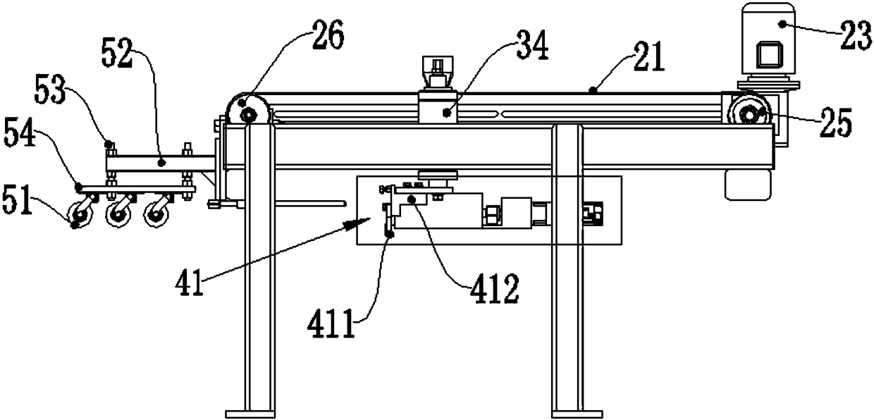
[0041] Such as figure 2As shown, the synchronous sliding unit 2 includes a sliding transmission belt 21 and a sliding drive module, the sliding transmission belt 21 is installed on the brick pusher frame 1, the sliding driving module is connected with the sliding transmission belt 21, The sliding drive module drives the sliding transmission...


PUM


Abstract

The invention discloses an automatic tile correction device. The automatic tile correction device comprises a tile pushing rack, a synchronous sliding unit, a tile pushing movable unit and a correction block unit. A sliding transmission belt drives a tile pushing sliding base to horizontally slide. A tile pushing lifting module drives a correction block installation plate to ascend or descend. A correction drive motor drives a first correction block to move horizontally. The automatic tile correction device is used for correcting tiles before a trimming working procedure is conducted, and therefore the diagonal errors of the tiles are reduced, the cutting precision is improved, and it is guaranteed that four sides of the tiles subjected to trimming are square; the tiles are pushed from the back sides, fine adjustment correction is achieved, no extrusion effect exists for the tiles, and the tiles are not damaged easily; and the automatic tile correction device can correct the tiles in different specifications, it is not need to adjust the installation positions of the correction block unit, and the production flexibility and adaptation are high.

Description

technical field [0001] The invention relates to the field of building ceramic production equipment, in particular to an automatic ceramic tile correction device. Background technique [0002] After the tiles are processed, there are burrs all around, which cannot meet the specified size requirements and precision, so the burrs must be removed first, which requires a tile edge trimmer to trim the tiles. In order to improve the edge trimming accuracy, a correction device is usually installed at the input end of the tile edge trimmer, so that the edge of the tile and the sliding track of the cutter are parallel to each other. However, the existing correction device is to set two correction blocks on the left and right sides of the tile conveyor belt respectively. The tile conveyor belt needs to be stopped, and then the centering correction is performed from the left and right sides of the tiles, and only one tile can be corrected at a time. , the correction efficiency is low; ...

Claims


Application Information

Patent Timeline
Patent Type & Authority Patents(China)
IPC IPC(8): B28D1/24B28D7/04B28D7/00
CPCB28D1/24B28D7/00B28D7/005B28D7/04
Inventor 杨扬叶金伟李松
Owner GUANGDONG SINID TECH
Learn More