
Processing Technology of Band Saw Base

A processing technology and technology of band sawing machine, which is applied in the field of processing technology of band sawing machine base, can solve problems such as poor firmness of band sawing machine, poor welding sealing performance of band sawing window, poor welding sealing performance, etc., and achieve detection Simple and convenient, increase the sealing performance, reduce the effect of mechanical deformation

Inactive Publication Date: 2019-06-11
宁波市甬塑机械制造有限公司
View PDF5 Cites 0 Cited by
  • Summary
  • Abstract
  • Description
  • Claims
  • Application Information

AI Technical Summary

Problems solved by technology

However, the base processing of the current band sawing machine generally has the defects of poor firmness and poor welding sealing. The poor firmness of the band sawing machine cannot effectively support the band sawing machine, and the poor welding and sealing performance of the band sawing window is easy Leakage of liquid in the water tank and oil tank of the band sawing machine

Method used


Image

  • Processing Technology of Band Saw Base
  • Processing Technology of Band Saw Base
  • Processing Technology of Band Saw Base

Examples


Embodiment Construction

[0037] The present invention will be described in further detail below in conjunction with the accompanying drawings.

[0038] A processing technology for a base of a band sawing machine, comprising the following steps:

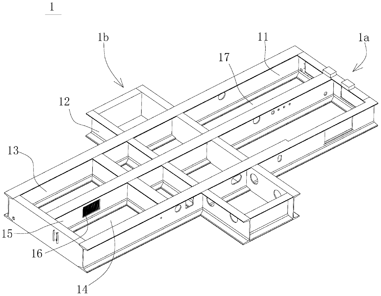
[0039] Refer to attached figure 1 , step a: welding three horizontal I-beams 11 and two vertical I-beams 12 to form a cross-shaped bottom frame 1 formed by interlacing the transverse section 1a and the longitudinal section 1b, and forming on the side of the transverse section 1a The two water tanks are the water storage tank 13 and the water outlet tank 14 which are adjacent to each other and communicate with each other. The water storage tank 13 and the water outlet tank 14 are separated by a partition 15, and a port is provided on the partition 15, and a filter screen is arranged on the port 16. The other side forms an oil tank 17.

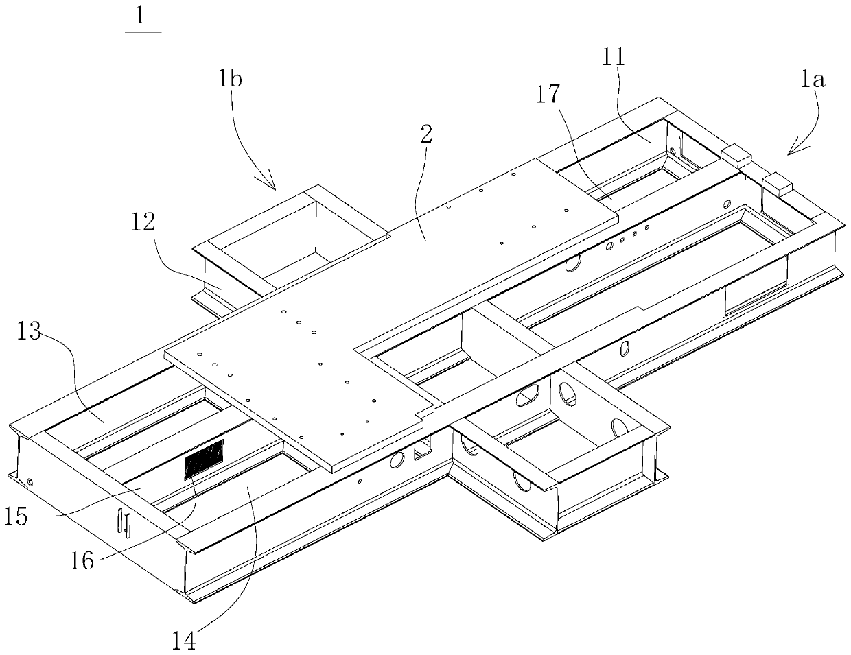
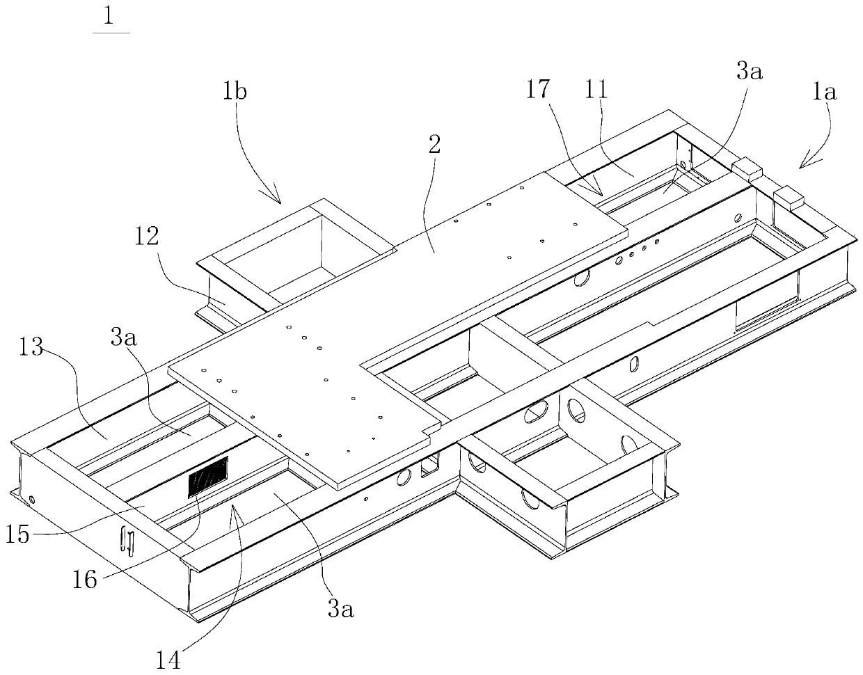
[0040] Refer to attached figure 2 , Step b: Weld a placement plate 2 on the upper surface of the bottom frame 1 correspo...


PUM


Abstract

The invention discloses a machining technology for a base of a band sawing machine. The machining technology overcomes the defects of poor firmness and poor welding sealing performance which generally exist during machining for the base of the band sawing machine at present. According to the technical scheme, the machining technology is characterized by comprising the steps that b, a placement plate is arranged at the position, corresponding to a movable clamp and a fixed clamp, of the upper surface of a bottom frame in a full welding manner; c, bottom plates are welded at the positions, at water tanks and an oil tank, on the lower surface of the bottom frame in a full welding manner; d, diesel oil is evenly smeared to the inner side walls of the water tanks and the oil tank and the interiors of the bottom plates, and the oil leakage phenomenon of weld cracks of the water tanks and the oil tank is checked after 50 min to 70 min; e, top plates are arranged at the positions, at the water tanks and the oil tank, on the upper surface of the bottom frame in a full welding manner; f, cover plates are arranged at the portion, besides the placement plate, on the longitudinal part of the bottom frame in a full welding manner; and g, adjusting plates which are horizontally arranged are evenly arranged at the positions, close to the side edge, of the bottom of the bottom frame, and reinforcing ribs are arranged at the positions of the side edge of the bottom frame. The beneficial effects that the band sawing machine is firm in structure, and gaps do not exist at welded positions are achieved.

Description

technical field [0001] The invention relates to a processing technique for a base of a band sawing machine. Background technique [0002] The bed of the band sawing machine is made of cast iron. When in use, the bed of the sawing machine is fixed on the base. The columns of the bed of the sawing machine are made of large and small columns (that is, the popular double The large circular column is used as the guide rail for the saw frame to support the up and down movement of the saw beam and ensure accurate guidance. The small column plays an auxiliary role to ensure the normal cutting of the saw blade. The middle is a clamping vise and a manual feeding mechanism. The front of the vise is connected to a workbench for receiving finished parts (referred to as the sawing machine bed). The clamping device on the left is a clamping screw that passes through the inner hole of the hydraulic clamping cylinder rod. Turn the hand wheel or press the button to make the left jaw move lef...

Claims


Application Information

Patent Timeline
Patent Type & Authority Patents(China)
IPC IPC(8): B23D55/00B23D53/00B23K33/00
CPCB23K33/002
Inventor 吴斌
Owner 宁波市甬塑机械制造有限公司
Learn More