Novel gas-liquid separation device
A gas-liquid separation device and gas-liquid separation technology are applied in the direction of separation methods, dispersed particle separation, chemical instruments and methods, etc., which can solve problems such as fiber mesh blockage or fouling, reduce manufacturing and operating costs, and improve The effect of removal efficiency and simple structure
- Summary
- Abstract
- Description
- Claims
- Application Information
AI Technical Summary
Problems solved by technology
Method used
Image

Examples
specific Embodiment approach 1
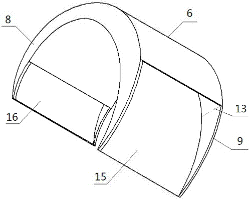
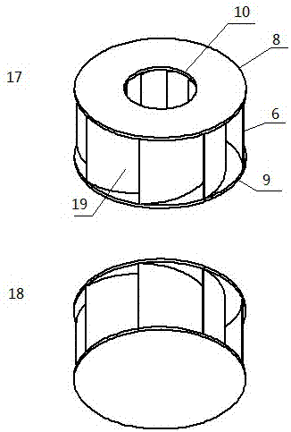
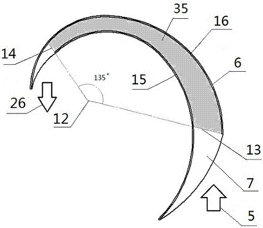
[0047] Such as figure 1 and Figure 5 As shown, the device is composed of a ring top cover (8), a circular bottom plate (9) and 8 spiral separators (6) (the geometric relationship is as follows figure 2 ); the outer diameter of the ring top cover is equal to the diameter of the circular bottom plate, the center of the circle (12) of the ring top cover and the circular bottom plate is coaxial and parallel to the plate surface, and 8 spiral separators (6) are arranged along the ring top cover (8 ) The rings are evenly rotated counterclockwise, the origin of each spiral coincides with the center of the circle, the height is the distance between the top cover and the bottom plate, and the upper and lower sides are connected with the ring top cover and the circular bottom plate; the section of the spiral separator is 2 adjacent The equiangular helical arm, the equal angle is 90°, the total rotation angle is 180° (that is, the golden spiral), the arc length ratio of the inner and ...
specific Embodiment approach 2
[0050] Such as Figure 6 and Figure 7 As shown, in the circular bottom plate (9) in Embodiment 1, a liquid discharge port (29) is added to form a circular bottom plate (25) with a liquid discharge port, and the diameter of the liquid discharge port is less than or equal to the diameter of the air outlet of the circular top cover , and connected to the liquid discharge cylinder (23). When in use, the outlet of the liquid discharge cylinder (24) is not below the liquid surface, which acts as a seal to prevent the leakage of the airflow from interfering with the separation area. After the gas-liquid separation, the liquid drops on the outer wall of the gas-liquid surface channel Converge upwards to form a stream, and the liquid flow is combined to the bottom of the channel and the center of the circular bottom plate under the joint action of gravity and air pressure, and flows out through the liquid discharge cylinder (23). Other implementation details are the same as those in ...
PUM
 Abstract
Description
Claims
Application Information
 - Generate Ideas
- Intellectual Property
- Life Sciences
- Materials
- Tech Scout
- Unparalleled Data Quality
- Higher Quality Content
- 60% Fewer Hallucinations
Browse by: Latest US Patents, China's latest patents, Technical Efficacy Thesaurus, Application Domain, Technology Topic, Popular Technical Reports.
© 2025 PatSnap. All rights reserved.Legal|Privacy policy|Modern Slavery Act Transparency Statement|Sitemap|About US| Contact US: help@patsnap.com