Low Noise Wide Dynamic Range Image Sensor Correlated Multiple Sampling Circuit
A wide dynamic range, image sensor technology, applied in the direction of image communication, television, electrical components, etc., can solve the problem of the reduction and reduction of the total dynamic range of the sensor
- Summary
- Abstract
- Description
- Claims
- Application Information
AI Technical Summary
Problems solved by technology
Method used
Image
Examples
Embodiment 1
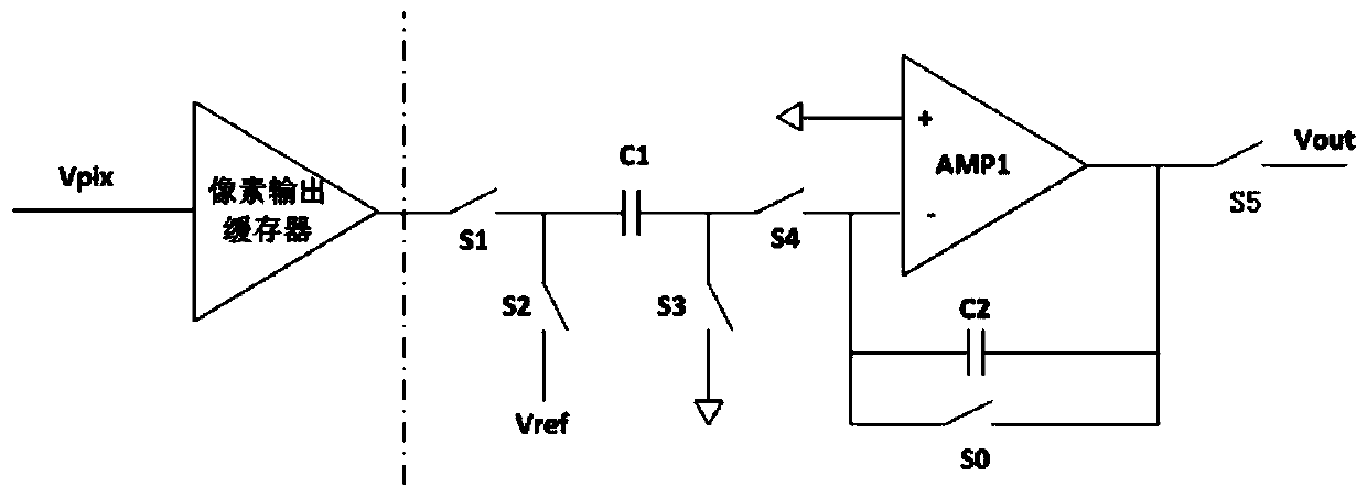
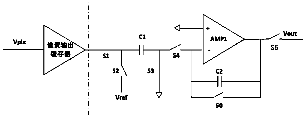
[0014] Such as figure 2 , 3 As shown, the low noise wide dynamic range image sensor related multiple sampling circuit of the present invention includes an integrator, an integral control unit, a readout control switch, an analog-to-digital conversion unit, and a data processing unit; the integral control unit includes a logic circuit and an analog Comparators.
[0015] The integrator receives and integrates the pixel signal Vpix output by the pixel output buffer; the analog comparator outputs the integration result Vpix output by each loop integrator i with the set voltage threshold V 0 are compared when V i less than V 0 When , the logic circuit outputs a signal to control the integrator to carry out the integration of the next cycle, when V i greater than or equal to V 0 When , the output signal of the logic circuit controls the readout control switch S5 to close so that the final integration result is transmitted to the analog-to-digital conversion unit, so that i at...
Embodiment 2
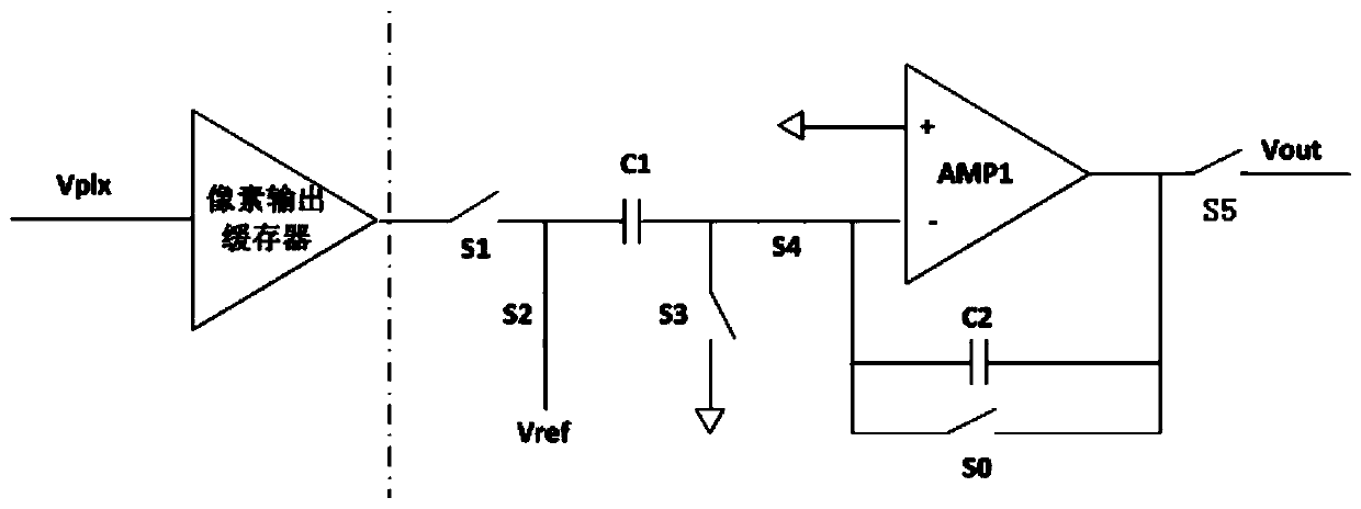
[0017] Such as figure 2 , 4 As shown, the low-noise wide dynamic range image sensor related multi-sampling circuit of the present invention includes an integrator, an integral control unit, a readout control switch, an analog-to-digital conversion unit, and a data processing unit; the integral control unit includes a logic circuit, an analog Digital conversion circuit and digital comparator.
[0018] The integrator receives and integrates the pixel signal Vpix output by the pixel output buffer; the analog-to-digital conversion circuit converts the integration result output by the integrator into a digital signal V i ’ and output to the digital comparator; the digital comparator will V i ’ with the set voltage threshold V 0 are compared when V i ’less than or equal to V 0 When , the logic circuit outputs a signal to control the integrator to carry out the integration of the next cycle, when V i greater than or equal to V 0 When , the output signal of the logic circuit c...
PUM
 Abstract
Description
Claims
Application Information
 - R&D Engineer
- R&D Manager
- IP Professional
- Industry Leading Data Capabilities
- Powerful AI technology
- Patent DNA Extraction
Browse by: Latest US Patents, China's latest patents, Technical Efficacy Thesaurus, Application Domain, Technology Topic, Popular Technical Reports.
© 2024 PatSnap. All rights reserved.Legal|Privacy policy|Modern Slavery Act Transparency Statement|Sitemap|About US| Contact US: help@patsnap.com


