Low-noise and wide-dynamic range image sensor related multi-sampling circuit
A wide dynamic range, image sensor technology, used in image communication, television, electrical components, etc., can solve the problem of reducing and reducing the total dynamic range of the sensor
- Summary
- Abstract
- Description
- Claims
- Application Information
AI Technical Summary
Problems solved by technology
Method used
Image
Examples
Embodiment 1
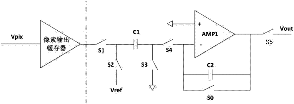
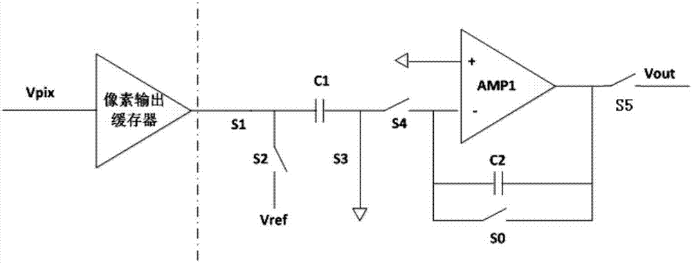
[0014] like figure 2 , 3 As shown, the low noise wide dynamic range image sensor related multiple sampling circuit of the present invention includes an integrator, an integral control unit, a readout control switch, an analog-to-digital conversion unit, and a data processing unit; the integral control unit includes a logic circuit and an analog Comparators.
[0015] The integrator receives and integrates the pixel signal Vpix output by the pixel output buffer; the analog comparator outputs the integration result Vpix output by each loop integrator i with the set voltage threshold V 0 are compared when V i less than V 0 When , the logic circuit outputs a signal to control the integrator to carry out the integration of the next cycle, when V i greater than or equal to V 0 When , the output signal of the logic circuit controls the readout control switch S5 to close so that the final integration result is transmitted to the analog-to-digital conversion unit, so that i at th...
Embodiment 2
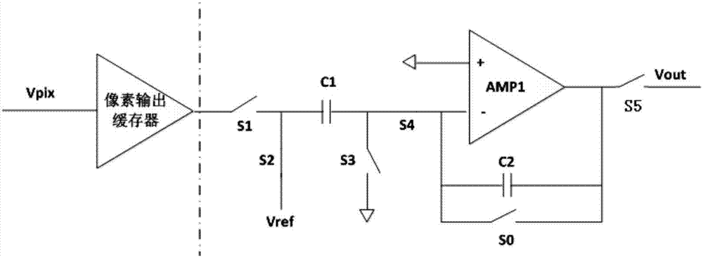
[0017] like figure 2 , 4 As shown, the low-noise wide dynamic range image sensor related multi-sampling circuit of the present invention includes an integrator, an integral control unit, a readout control switch, an analog-to-digital conversion unit, and a data processing unit; the integral control unit includes a logic circuit, an analog Digital conversion circuit and digital comparator.
[0018] The integrator receives and integrates the pixel signal Vpix output by the pixel output buffer; the analog-to-digital conversion circuit converts the integration result output by the integrator into a digital signal V i ’ and output to the digital comparator; the digital comparator will V i ’ with the set voltage threshold V 0 are compared when V i ’less than or equal to V 0 When , the logic circuit outputs a signal to control the integrator to carry out the integration of the next cycle, when V i greater than or equal to V 0 When , the output signal of the logic circuit cont...
PUM
 Abstract
Description
Claims
Application Information
 - R&D
- Intellectual Property
- Life Sciences
- Materials
- Tech Scout
- Unparalleled Data Quality
- Higher Quality Content
- 60% Fewer Hallucinations
Browse by: Latest US Patents, China's latest patents, Technical Efficacy Thesaurus, Application Domain, Technology Topic, Popular Technical Reports.
© 2025 PatSnap. All rights reserved.Legal|Privacy policy|Modern Slavery Act Transparency Statement|Sitemap|About US| Contact US: help@patsnap.com


