
Engine dismounting video observation device

An observation device and engine technology, applied in the direction of TV, color TV, closed-circuit television system, etc., can solve the problems of inconvenient use and operation, narrow space gap, low application efficiency, etc., to improve the degree of automation and reliability, and the degree of automation High, the effect of improving work efficiency

Active Publication Date: 2017-07-14
SHENYANG AIRCRAFT CORP
View PDF3 Cites 0 Cited by
  • Summary
  • Abstract
  • Description
  • Claims
  • Application Information

AI Technical Summary

Problems solved by technology

[0003] As the core power unit of the aircraft, the installation of the engine is the top priority of the assembly work. However, due to its large mass, large size, complex structure, and narrow installation space, it is difficult to realize the engine in the existing installation mode. The high-efficiency and high-quality installation lacks effective installation methods, and there is a big gap compared with foreign advanced digital installation technologies and methods
There are many external pipelines of the engine body, and the external shape and structure are very complicated. At present, during the engine installation process, the observation of the installation gap and whether it collides with and interferes with the engine installation compartment is mostly carried out by visual observation at the observation port through the lighting lamp. , due to the narrow space and insufficient lighting, the observation effect is poor, and the collision between the engine and the installation cabin is easy to occur, resulting in dangerous accidents
At the same time, some of the existing video observation devices are relatively large, cumbersome, inefficient, inconvenient to use and operate, and have a great impact on the quality and efficiency of engine installation. Therefore, it is necessary to provide an efficient and convenient engine disassembly video The observation device and method further improve the quality and efficiency of gap observation in the engine installation process, and ensure the safety, reliability and stability of engine installation

Method used


Image

  • Engine dismounting video observation device
  • Engine dismounting video observation device

Examples


Embodiment

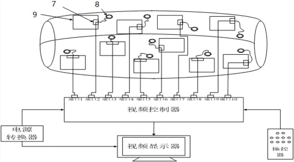
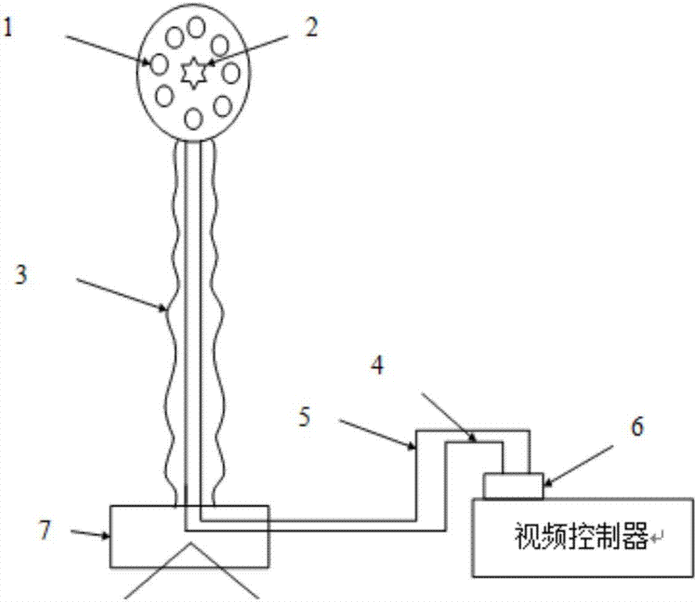
[0020] The observation device is composed of a video unit, a mounting clip, a video controller, a video display, a manipulator, a power converter, etc., wherein the video unit includes an LED light source, a video head, a flexible bending rod, a data line, and a power line. Arrange 10 video units at the observation port of the engine installation cabin, and fix the video units with mounting clips for effective installation. At the same time, connect the power line and data line of each video unit with the port 1 to port 10 of the video controller. Make electrical connections, and at the same time connect the video controller with the power converter, video display, and controller to form an overall structure to achieve effective observation of the system.

[0021] As the information collection of the observation device and the input of video information, the video unit is composed of a video head, LED light source, flexible bending rod, power line, and data line light. The vide...


PUM


Abstract

The present invention belongs to the sensing detection and device technology field, and provides an engine dismounting video observation device. The device comprises a video unit, an installation clamp, a video controller, a video display, a controller and a power adapter. The video unit is connected with the port of the video controller through a data line and a power line and is fixed at the viewing port of an engine installation cabin through the installation clamp; the video controller processes images collected by the video unit and is connected with the video display, the controller and the power adapter; the video display is taken as the display output of the engine dismounting video observation device; the controller is taken as the operation input of the engine dismounting video observation device; and the power adapter is taken as the power supply of the engine dismounting video observation device. The engine dismounting video observation device realizes remote video observation to improve the system automation degree and reliability, relieve manual operation burden and improve work efficiency.

Description

technical field [0001] The invention belongs to the technical field of sensing detection and devices, and in particular relates to a video observation device for engine disassembly and assembly. [0002] technical background [0003] As the core power unit of the aircraft, the installation of the engine is the top priority of the assembly work. However, due to its large mass, large size, complex structure, and narrow installation space, it is difficult to realize the engine in the existing installation mode. Compared with the advanced digital installation technology and methods abroad, there is a big gap. There are many external pipelines of the engine body, and the external shape and structure are very complicated. At present, during the engine installation process, the observation of the installation gap and whether it collides with and interferes with the engine installation compartment is mostly carried out by visual observation at the observation port through the lightin...

Claims


Application Information

Patent Timeline
Patent Type & Authority Applications(China)
IPC IPC(8): H04N7/18H04N5/268
CPCH04N5/268H04N7/181Y02W30/56
Inventor 李文强潘新
Owner SHENYANG AIRCRAFT CORP
Learn More