
Rotor part of variable-frequency motor, and variable-frequency motor

A variable frequency motor and rotor technology, applied in the direction of magnetic circuit rotating parts, electrical components, electric components, etc., can solve the problems of reduced manufacturing costs and increased types of materials, and achieve the goals of reducing the number of materials, expanding the scope of application, and reducing manufacturing costs Effect

Pending Publication Date: 2017-07-14
ANHUI MEIZHI COMPRESSOR +1
View PDF0 Cites 6 Cited by
  • Summary
  • Abstract
  • Description
  • Claims
  • Application Information

AI Technical Summary

Problems solved by technology

In the related art, in the production of these two rotor parts, in order to prevent the limit boss of the rotor end plate from touching the rotor core, it is necessary to design two sets of rotor end plates, which will lead to an increase in the types of materials, which is not conducive to the reduction of manufacturing costs

Method used


Image

  • Rotor part of variable-frequency motor, and variable-frequency motor
  • Rotor part of variable-frequency motor, and variable-frequency motor
  • Rotor part of variable-frequency motor, and variable-frequency motor

Examples


Embodiment Construction

[0030] Embodiments of the present invention are described in detail below, examples of which are shown in the drawings, wherein the same or similar reference numerals designate the same or similar elements or elements having the same or similar functions throughout. The embodiments described below by referring to the figures are exemplary only for explaining the present invention and should not be construed as limiting the present invention.

[0031] In describing the present invention, it is to be understood that the terms "vertical", "horizontal", "top", "bottom", "inner", "outer", "axial", "radial", "circumferential" ” and other indicated orientations or positional relationships are based on the orientations or positional relationships shown in the accompanying drawings, which are only for the convenience of describing the present invention and simplifying the description, rather than indicating or implying that the referred device or element must have a specific orientation...


PUM


Abstract

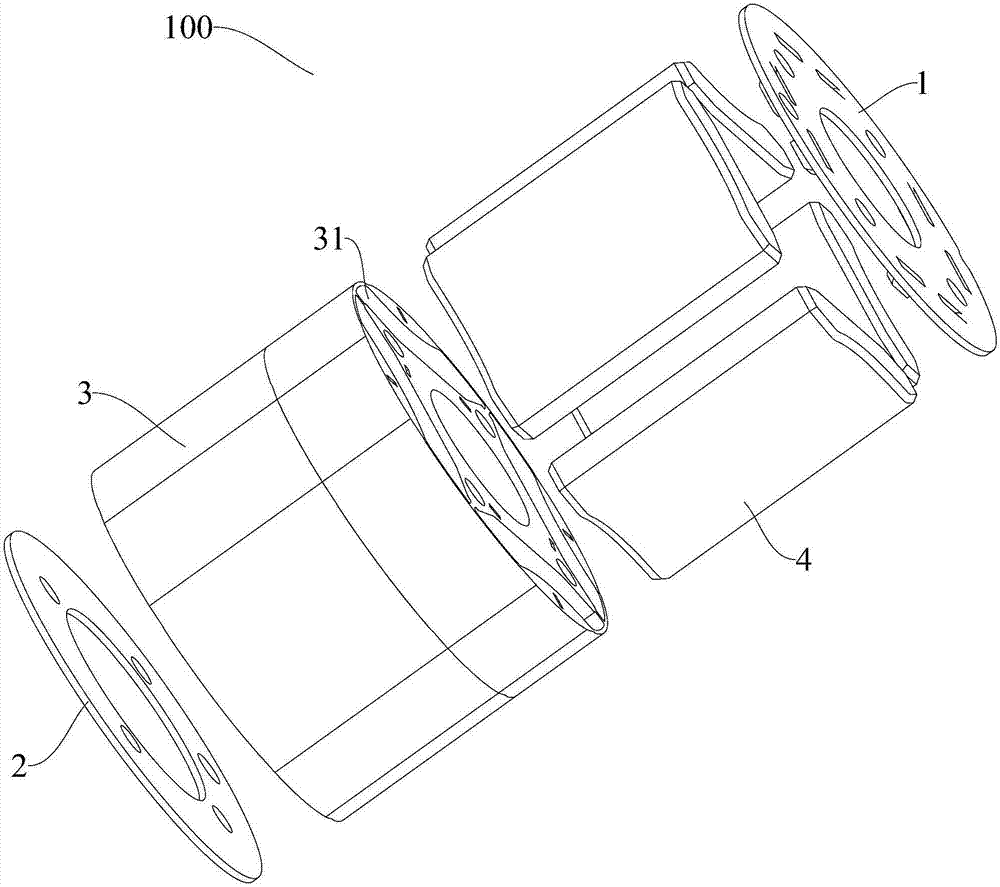
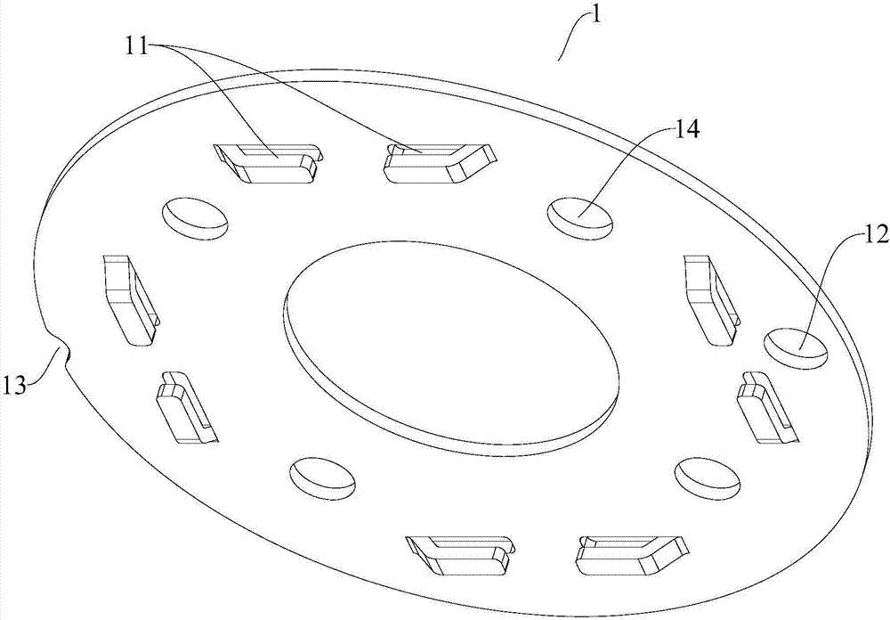
The invention discloses a rotor part of a variable-frequency motor, and the variable-frequency motor. The rotor part of the variable-frequency motor comprises a rotor iron core, a rotor magnet, a first rotor end plate and a second rotor end plate; a magnet groove is arranged in the rotor iron core; furthermore, the magnet groove is one selected from a first groove and a second groove; the rotor magnet is one selected from a first permanent magnet and a second permanent magnet, and installed in the magnet groove; a limiting lug boss for blocking the rotor magnet is arranged on the first rotor end plate, wherein the rotor magnet respectively has a first projection or a second projection on the first rotor end plate when the rotor magnet is the first permanent magnet or the second permanent magnet; and the limiting lug boss is arranged in the overlap area of the first projection and the second projection. By means of the rotor part of the variable-frequency motor in the embodiment of the invention, the first rotor end plate having the above structural form is designed, so that the application range of the first rotor end plate can be enlarged; therefore, the material number can be reduced; and the manufacturing cost can be reduced.

Description

technical field [0001] The invention belongs to the technical field of motor manufacturing, and in particular relates to a rotor component of a variable frequency motor and a variable frequency motor with the rotor component. Background technique [0002] The variable frequency motor of the refrigerator compressor has rotor components, and the rotor components often use two types of rotor magnets: ferrite permanent magnets and rare earth permanent magnets, to meet the requirements of different magnetic flux densities under the same inner and outer diameter of the rotor. Due to the difference in material properties between the ferrite permanent magnet and the rare earth permanent magnet, the size of the rotor magnet corresponding to the two rotor parts and the size of the magnet slot on the rotor core are different. In the related art, in the production of these two rotor parts, in order to prevent the limit boss of the rotor end plate from touching the rotor core, it is nece...

Claims


Application Information

Patent Timeline
IPC IPC(8): H02K1/27H02K1/28
CPCH02K1/276H02K1/28
Inventor 徐奔胡慧军
Owner ANHUI MEIZHI COMPRESSOR
Learn More