
Rail type iron roughneck

An iron driller and rail-type technology, which is applied to drill pipes, drill pipes, drilling equipment, etc., can solve the problems of prolonging operation time, affecting the degree of automation, and not compensating horizontal displacement, etc., so as to reduce operating time, increase working range, Avoid the effects of corrective stress

Pending Publication Date: 2017-07-14
SHANGHAI ZHENHUA HEAVY IND
View PDF21 Cites 13 Cited by
  • Summary
  • Abstract
  • Description
  • Claims
  • Application Information

AI Technical Summary

Problems solved by technology

[0006] 2. The turnbuckle pliers are equipped with a vertical displacement compensation mechanism to compensate the vertical displacement of the turnbuckle device, but there is no device for compensating the horizontal displacement. When the pipe has an inclination angle in the vertical direction, the inclination angle will cause The deviation between the position of the pipe fitting and the center of the clamp in the horizontal direction results in a loss of clamping effect;
[0007] 3. There is no cleaning device, and external equipment is needed to clean the butt-connected threads, which prolongs the working time and affects the degree of automation;
[0008] 4. There is no mud blowout prevention device. After the shackle is completed, the iron driller needs to exit first, and then use external equipment to collect the mud sprayed under high pressure, which prolongs the working time, and the iron driller needs to withdraw to the initial stage. The mud blowout preventer device can only enter after the position, which makes the safe space around the wellhead also compressed
However, in this application, the position of the mud blowout preventer is relatively close to the clamp, which will affect the operator's observation of the operation process of the clamp

Method used


Image

  • Rail type iron roughneck
  • Rail type iron roughneck
  • Rail type iron roughneck

Examples


Embodiment Construction

[0108] The implementation of the present invention will be illustrated by specific specific examples below, and those skilled in the art can easily understand other advantages and effects of the present invention from the content disclosed in this specification. Although the description of the invention will be presented in conjunction with a preferred embodiment, it is not intended that the features of the invention be limited to that embodiment only. On the contrary, the purpose of introducing the invention in conjunction with the embodiments is to cover other options or modifications that may be extended based on the claims of the present invention. The following description contains numerous specific details in order to provide a thorough understanding of the present invention. The invention may also be practiced without these details. Also, some specific details will be omitted from the description in order to avoid obscuring or obscuring the gist of the present inventio...


PUM


Abstract

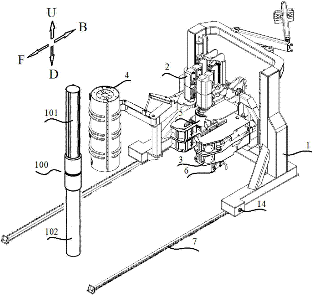
The invention relates to a rail type iron roughneck, which is used for performing screwing and / or unscrewing operation on an upper part pipe fitting and a lower part pipe fitting. The rail type iron roughneck is characterized by comprising a rail, a base, a spinning wrench and an upper unscrewing wrench, wherein the base can move forwards to the work position along the rail or can move backwards so as to be far away from the work position; the spinning wrench is arranged on the base; the upper unscrewing wrench is arranged on the base and is positioned under the spinning wrench. The iron roughneck related by the invention is the rail type iron roughneck. Compared with a cantilever type iron roughneck, the rail type iron roughneck breaks through the limitation of the cantilever length on the work range; the work range of the iron roughneck is obviously increased.

Description

technical field [0001] The invention relates to a drilling and workover equipment, in particular to a rail-type iron driller. Background technique [0002] During the drilling process and maintenance process of oil and oil wells, the tools used to complete the make-up and break-out of drilling tools usually include hydraulic tongs and telescopic arm type iron drillers. The commonly used tool for making and breaking breakouts in practice is hydraulic tongs, but the degree of automation of hydraulic tongs is low, and the labor intensity of the operator is high; later, a telescopic arm type iron driller with a high degree of automation was developed, which can reduce the strength of the laborers, but Due to the limitation of arm length, the working distance is limited. [0003] The Chinese patent document CN 202689976 U that the applicant has been authorized discloses a cantilever type iron driller, comprising: a column base; a telescopic arm, one end of which protrudes from t...

Claims


Application Information

Patent Timeline
IPC IPC(8): E21B19/16E21B41/00
CPCE21B19/16E21B41/00
Inventor 王可竹吴富生许素蕾冯浩吴建奎朱代兴
Owner SHANGHAI ZHENHUA HEAVY IND
Learn More